
A Noise Suppression Device for Weapon Compartment Based on Ambient Gas Jet Flow

A noise suppression and ambient gas technology, applied in the aerospace field, can solve the problems of reduced noise reduction ability of the device, small application range, failure of electronic control equipment, etc., and achieve the effect of reducing noise intensity, obvious noise reduction effect, and weight reduction

Active Publication Date: 2018-10-19
INST OF HIGH SPEED AERODYNAMICS OF CHINA AERODYNAMICS RES & DEV CENT
View PDF9 Cites 0 Cited by
  • Summary
  • Abstract
  • Description
  • Claims
  • Application Information

AI Technical Summary

Problems solved by technology

The high-intensity noise environment not only has a destructive effect on the weapon compartment system, such as causing the failure of the electronic control equipment in the compartment, fatigue of the bulkhead structure, etc., but also increases the maintenance cost of the fighter
[0004] At present, the noise suppression devices used in aircraft weapon compartments mainly include leading edge spoilers and micro-hole jets. The disadvantage of the former is that the spoilers destroy the shape of the aircraft, increase flight resistance, and its scope of application is small. Under the condition of supersonic flight, the noise reduction ability of the device is significantly reduced or even fails; the disadvantage of the latter is that the micro-hole jet requires an additional high-pressure air supply, which is not only inconvenient to carry, but also the flow rate of the jet outlet is affected by the air source. Resulting in limited usage time of the noise reduction device

Method used


Image

  • A Noise Suppression Device for Weapon Compartment Based on Ambient Gas Jet Flow
  • A Noise Suppression Device for Weapon Compartment Based on Ambient Gas Jet Flow
  • A Noise Suppression Device for Weapon Compartment Based on Ambient Gas Jet Flow

Examples


Embodiment 1

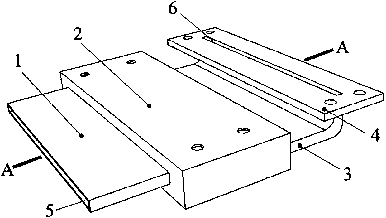
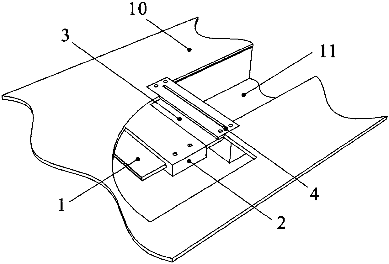
[0044] A kind of weapon compartment noise suppression device based on ambient gas jet flow of the present embodiment, such as figure 1 As shown, it includes the resident chamber 2 and the jet outlet cover 4 arranged at the outlet end of the resident chamber 2. The jet outlet cover 4 has a jet outlet 6 with a slender rectangular cross section and the position of the jet outlet 6 corresponds to the weapon compartment 11. leading edge. The structure of the resident chamber 2 with a small mouth and a large cavity means that the cross-sections of the inlet and outlet openings of the resident chamber 2 are smaller than the cross-section of the inner cavity of the resident chamber 2 . The resident chamber 2 has a small mouth and a large cavity, and along the airflow direction, the ambient gas enters into the resident chamber 2 and expands.

[0045] working principle:

[0046] Such as image 3 As shown, the present invention is installed on the front edge model platform 10 of the w...

Embodiment 2

[0048] A weapon compartment noise suppression device based on ambient gas jet flow, comprising a chamber 2 with a small mouth and a large cavity connected along the airflow direction and a jet flow opening cover 4 with a jet flow outlet 6, the cross section of which is a slender rectangular jet flow The exit 6 is located at the front edge of the weapons bay 11 . The chamber of the resident chamber 2 is successively divided into a resident chamber inlet 7, a main chamber 12, and a resident chamber outlet 8 along the airflow direction, and the cross sections of the resident chamber inlet 7 and the resident chamber outlet 8 are both rectangular.

[0049] The opening positions of the resident entrance 7 and the resident outlet 8 can be at the same height, or they can be arranged in a staggered manner. Usually, the resident entrance 7 is slightly larger than the resident outlet 8 and the resident inlet 7 and the resident outlet 8 are at the same height or slightly higher.

[0050]...

Embodiment 3

[0058] This embodiment is further optimized on the basis of Embodiment 1 and Embodiment 2. Further, when the noise suppression device is in a normal installation state, the longitudinal section along the vertical direction and passing through the central axis is a longitudinal section, and the main chamber 12. The contour in the longitudinal section is composed of the inlet dividing line, the upper contour line, the outlet dividing line and the lower contour line connected end to end in sequence.

[0059] Such as Figure 4 , Figure 5 As shown, the contour line of the main chamber 12 in the longitudinal section is separated by the inlet dividing line L connected end to end 1 , upper contour line L 2 , exit dividing line L 3 , the lower contour line L 4 Composition, upper contour line L 2 The end point at the entrance 7 of the resident room is M, the end point at the exit 8 of the resident room is N, and the upper contour line L 2 It is a spline curve whose middle part is...


PUM


Abstract

The invention discloses a weapon bay noise suppression device based on environment gas jet. The weapon bay noise suppression device is installed at an opening of a weapon bay (11) and comprises a plenum chamber (2) which is connected along an airflow direction and is provided with a small opening and a large cavity, and a jet flow opening cover (4) provided with a jet flow outlet (6), wherein the jet flow outlet (6) with long and thin rectangular cross section is positioned at the front edge of the weapon bay (11). The weapon bay noise suppression device is installed inside the weapon bay, environment gas is utilized as an air source, the intensity of noise in the bay when the weapon bay is started is reduced by spraying gas flow to the opening of the weapon bay, the aerodynamic configuration of an aircraft cannot be damaged, also high-pressure air source does not need to be additionally supplied, the service life is long, and stable and reliable effects are achieved.

Description

technical field [0001] The invention relates to the field of aerospace technology, in particular to a weapon compartment noise suppression device based on ambient gas jet flow. Background technique [0002] Modern military fighters generally use weapons bays to carry weapons. This is because when the fighters are in the state of takeoff / landing, cruise, etc., the door of the weapons bay is closed. This method of carrying weapons can effectively improve the flight performance of fighters, such as improving stealth. capability, enhanced maneuverability, reduced flight resistance, etc. [0003] When the fighter plane launches or drops weapons, the hatch of the weapon compartment is open. Due to the high flow rate of the ambient gas and the low flow rate of the gas in the weapon compartment, a transition layer will be formed in the opening area of ​​the weapon compartment between gases with different flow rates. The gas is called the shear layer. When the shear layer hits the ...

Claims


Application Information

Patent Timeline
Patent Type & Authority Patents(China)
IPC IPC(8): B64D7/00B64C23/00
CPCB64C23/00B64D7/00
Inventor 王显圣郑晓东路波吴军强杨党国张征宇吴继飞杨可刘俊
Owner INST OF HIGH SPEED AERODYNAMICS OF CHINA AERODYNAMICS RES & DEV CENT
Learn More