
Centrifugal compressor and air conditioner provided with same

A centrifugal compressor, centrifugal impeller technology, applied in the direction of machine/engine, mechanical equipment, liquid fuel engine, etc., can solve problems such as large axial force

Active Publication Date: 2017-01-18
GREE ELECTRIC APPLIANCES INC
View PDF7 Cites 4 Cited by
  • Summary
  • Abstract
  • Description
  • Claims
  • Application Information

AI Technical Summary

Problems solved by technology

[0005] The main purpose of the present invention is to provide a centrifugal compressor and an air conditioner with it, to solve the problem that the rotor of the centrifugal compressor in the prior art is subjected to a relatively large axial force

Method used


Image

  • Centrifugal compressor and air conditioner provided with same
  • Centrifugal compressor and air conditioner provided with same
  • Centrifugal compressor and air conditioner provided with same

Examples


Embodiment Construction

[0023] It should be noted that, in the case of no conflict, the embodiments in the present application and the features in the embodiments can be combined with each other. The present invention will be described in detail below with reference to the accompanying drawings and examples.

[0024] The following will clearly and completely describe the technical solutions in the embodiments of the application with reference to the drawings in the embodiments of the application. Apparently, the described embodiments are only some of the embodiments of the application, not all of them. The following description of at least one exemplary embodiment is merely illustrative in nature and in no way serves as any limitation of the application, its application or uses. Based on the embodiments in this application, all other embodiments obtained by persons of ordinary skill in the art without creative efforts fall within the scope of protection of this application.

[0025] It should be not...


PUM


Abstract

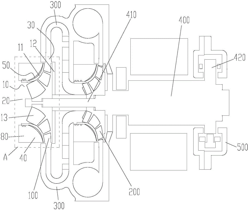
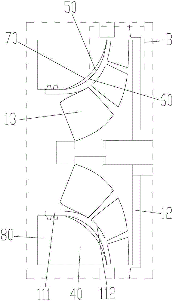
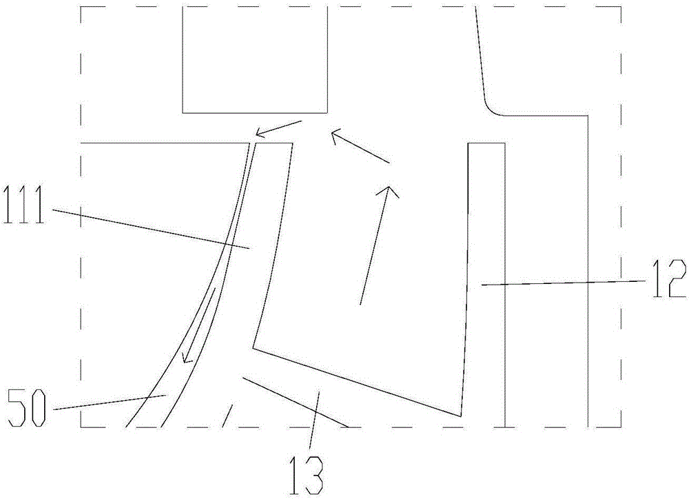
The invention provides a centrifugal compressor and an air conditioner provided with the same. The centrifugal compressor comprises centrifugal impellers, sealing rings and annular structures. Each centrifugal impeller comprises a first end plate, a second end plate and blades arranged between the first end plate and the second end plate. A refrigerant inlet is formed in each first end plate. A refrigerant outlet is formed between the circumferential edge of each first end plate and the circumferential edge of the corresponding second end plate. Each sealing ring is arranged on the circumferential outer side of the corresponding first end plate and sealed in the position of the corresponding refrigerant inlet. Each annular structure is arranged on the side, facing the corresponding second end plate, of the corresponding sealing ring. A buffer cavity is formed between each annular structure and the corresponding first end plate. By the adoption of the technical scheme, the problem that in the prior art, the axial force borne by a rotor of a centrifugal compressor is large is solved.

Description

technical field [0001] The invention relates to the technical field of refrigeration equipment, in particular to a centrifugal compressor and an air conditioner with the same. Background technique [0002] When the centrifugal compressor is running, it creates a pressure differential within the centrifuge system. Specifically, the refrigerant enters the centrifugal impeller from the front end and is discharged from the side of the centrifugal impeller. Since the pressure of the refrigerant leaving the impeller is greater than the pressure of the refrigerant entering the impeller, the refrigerant will flow into the front end plate of the centrifugal impeller along the pressure difference and exert pressure on the front end plate. Under the action of the above pressure, the rotor of the motor will be subjected to an axial force, which will cause the compressor to deviate in the axial direction during operation. [0003] In the prior art, in order to prevent the rotor from be...

Claims


Application Information

Patent Timeline
Patent Type & Authority Applications(China)
IPC IPC(8): F04D29/28F04D29/08F04D29/051F04D29/66
CPCF04D29/051F04D29/083F04D29/284F04D29/286F04D29/662F04D29/666
Inventor 刘增岳钟瑞兴陈玉辉蒋楠刘建飞蒋彩云周义雷连冬
Owner GREE ELECTRIC APPLIANCES INC
Learn More