Dummy load circuit

A dummy load and circuit technology, applied in the field of power supply testing, can solve problems such as unstable output oscillation and large ripple

Active Publication Date: 2017-01-18
CHNEGDU CHIFFO ELECTRONICS INSTR
View PDF9 Cites 1 Cited by
  • Summary
  • Abstract
  • Description
  • Claims
  • Application Information

AI Technical Summary

Problems solved by technology

[0003] The purpose of the present invention is to solve the problem that the output oscillation is unstable and the ripple becomes larger when each power module in the DC power analyzer outputs a small voltage

Method used


Image

  • Dummy load circuit
  • Dummy load circuit

Examples


Embodiment 1

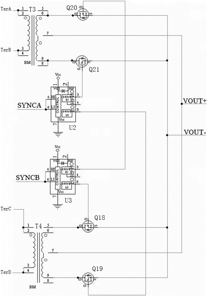
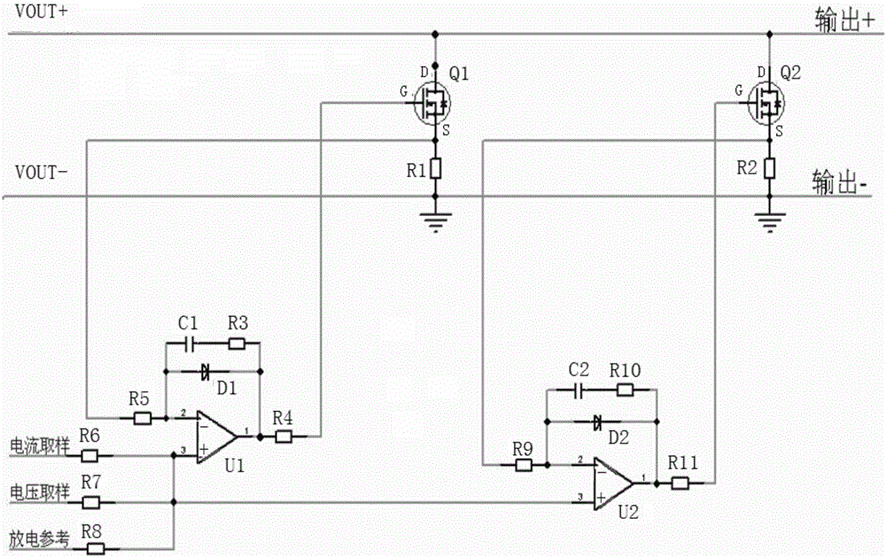
[0022] Embodiment 1: as figure 1 As shown, this embodiment provides a dummy load circuit, the dummy load circuit includes a first sub-dummy load circuit and a second sub-dummy load circuit connected in parallel; the first sub-dummy load circuit and the second sub-dummy load circuit The circuit is set as figure 2 Between the output terminals VOUT+ and VOUT- of the power conversion module in the shown power module;

[0023] The first sub-dummy load circuit includes a first controllable switch Q1, a second operational amplifier U1, and a first resistor R1 connected in series with the first Q1 controllable switch; the source of the first controllable switch Q1 is connected to the The first resistor R1 is connected, and the source of the first controllable switch Q1 is also connected to the inverting output terminal of the second operational amplifier U1 through the fifth resistor R5; the non-inverting input of the second operational amplifier U1 terminal and the positive phase ...


PUM


Abstract

The invention relates to the field of a power supply circuit and especially relates to a dummy load circuit. The provided dummy load circuit used for a voltage analyzer voltage module, when small voltages are output, is controlled by internal discharge currents and a discharge reference, and when the output voltages are increased or a load is externally accessed, is commonly controlled by voltage sampling and current sampling. When loads are increased to a certain degree, an internal load stops working. In such a way, a power supply can realize stable-voltage output in case of no loads, and output power in case of full loads is also not affected; and the problems of unstable output oscillation and increased ripples, caused by PWM discontinuity due to incapability of an energy storage inductor in working to a CCM mode if a PWM duty ratio is decreased to a minimum value when the power supply is zero loaded are effectively solved.

Description

technical field [0001] The invention relates to the field of power supply testing, in particular to a dummy load circuit. Background technique [0002] Usually, when conducting tests related to DC power supplies, engineers must assemble and configure multiple instruments to complete the DC power supply and measurement tasks. When performing these complex tasks, multiple test instruments may be connected at the same time, thereby increasing the risk of errors; for this reason, engineers may choose automatic testing that is far more complicated than manual testing, but automated testing tasks will reduce manual errors, but writing and debuggers add further workload to already overworked R&D engineers. The emergence of DC power analyzers avoids the need for engineers to use multiple devices and perform complex debugging before testing. The power analyzer can measure the current flowing into the DUT through its built-in current dynamic measurement capability, without the need ...

Claims


Application Information

Patent Timeline
Patent Type & Authority Applications(China)
IPC IPC(8): G01R31/40
CPCG01R31/40Y02B70/10
Inventor 蒋承武管邦伟
Owner CHNEGDU CHIFFO ELECTRONICS INSTR
Why Eureka
Try Eureka