Diesel engine exhaust aftertreatment device

A technology for after-treatment of exhaust gas and diesel engine, which is applied in the direction of exhaust device, muffler device, mechanical equipment, etc. It can solve the problems of easy crystallization, increase of maintenance and repair costs, reduction of vehicle cab space or trunk volume, etc., to achieve Strengthen the purification effect and increase the oxidation surface area

Inactive Publication Date: 2021-06-29
HEBEI NORMAL UNIV
View PDF9 Cites 0 Cited by
  • Summary
  • Abstract
  • Description
  • Claims
  • Application Information

AI Technical Summary

Problems solved by technology

[0003] However, the above measures will have the following disadvantages: First, during the regeneration process of the particulate matter trap, increasing the temperature of the exhaust gas of the diesel engine will seriously shorten the life of the oxidation catalytic converter upstream of the particulate matter trap
Second, the selective catalytic converter requires a complex urea injection system, and urea is easy to crystallize on the carrier of the selective catalytic converter in a low temperature environment. In order to ensure the normal operation of the urea injection system, the urea aqueous solution needs to be heated, and Sulfur contained in fuel oil tends to deactivate oxidation catalytic converters and selective catalytic converters
3. The combined use of multiple devices makes the structure of the diesel engine exhaust aftertreatment system complex, resulting in a significant reduction in the vehicle cab space or trunk volume
Fourth, the complex exhaust after-treatment system increases maintenance and repair costs
"A Diesel Engine Exhaust Gas Low-Temperature Plasma Assisted Catalytic Conversion Purification Device" disclosed in CN201620546505.2, although the particulate matter, hydrocarbons, carbon monoxide, and nitrogen oxides in the diesel engine exhaust gas are purified, and the diesel engine exhaust post-treatment device is simplified, the particulate matter Purification efficiency is relatively low

Method used


Image

  • Diesel engine exhaust aftertreatment device
  • Diesel engine exhaust aftertreatment device
  • Diesel engine exhaust aftertreatment device

Examples


Embodiment Construction

[0021] In order to make the purpose, technical solutions and advantages of the embodiments of the present invention clearer, the technical solutions of the present invention are clearly and completely described below in conjunction with the accompanying drawings in the embodiments of the present invention. Obviously, the described embodiments are the embodiment of the present invention Some, but not all, embodiments. Based on the embodiments of the present invention, all other embodiments obtained by persons of ordinary skill in the art without making creative efforts belong to the protection scope of the present invention.

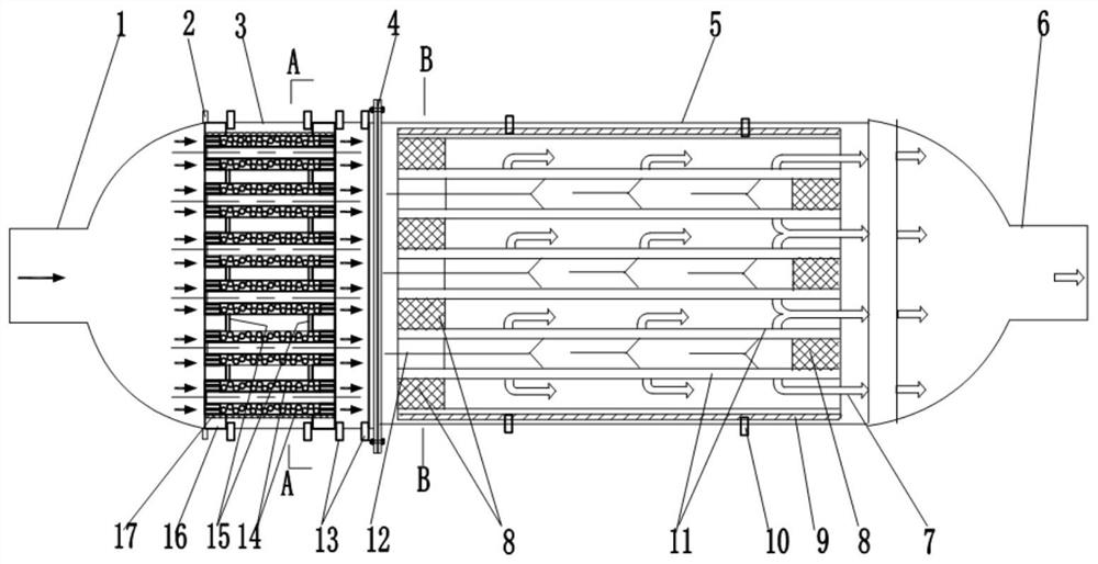
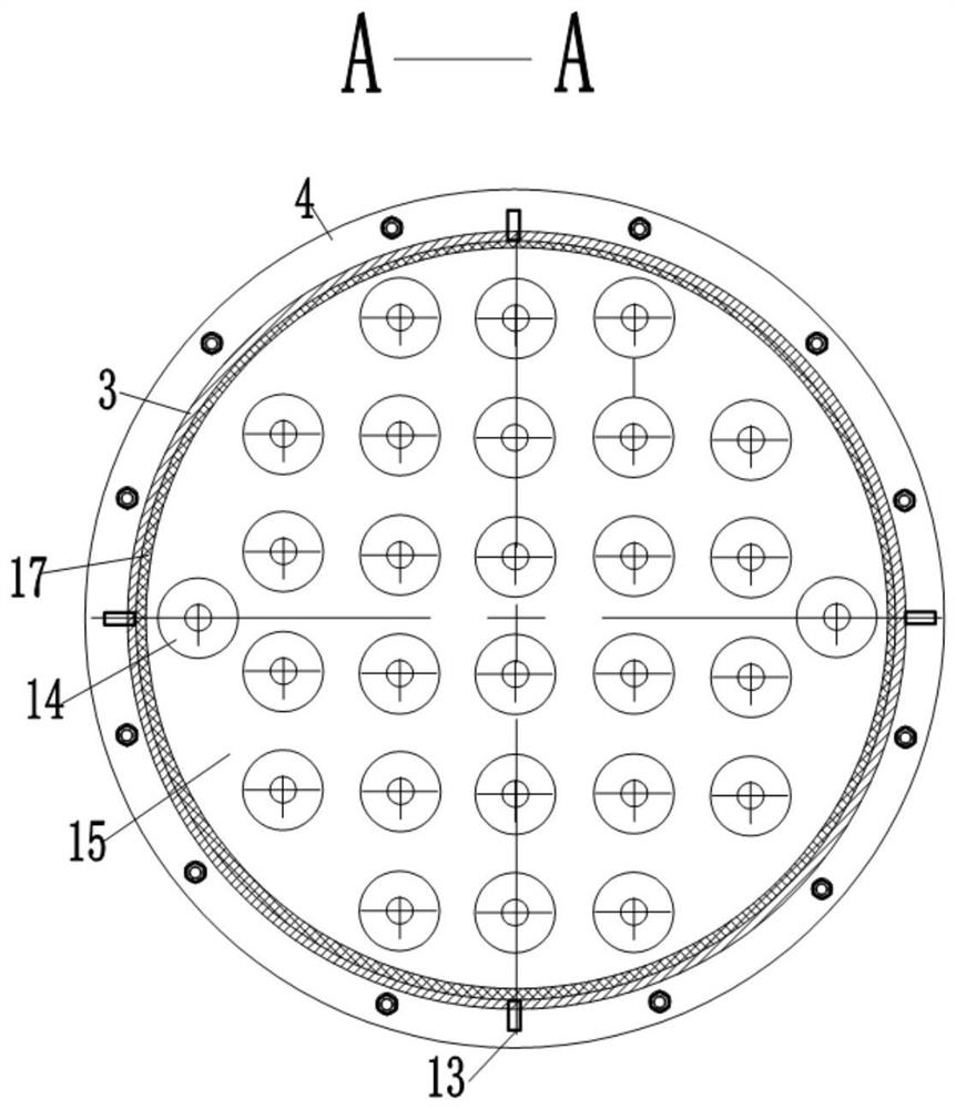
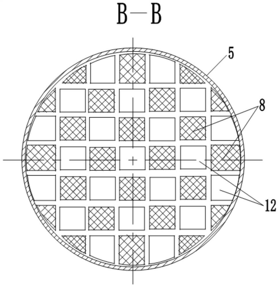
[0022] Such as Figure 1~5 As shown, the post-treatment process of diesel engine exhaust in the present invention: 1. Turn on the power supply to make the discharge between the outer sleeve electrode 20 and the inner sleeve electrode 21 produce ionization, and the exhaust gas of the diesel engine enters the left part through the air inlet 1 The sleeve 3 ...


PUM


Abstract

The invention discloses a diesel engine exhaust aftertreatment device. The diesel engine exhaust aftertreatment device comprises an insulating cylinder, a plasma discharging body, a porous disc, an external insulator and a catalyst carrier which are arranged in a left sleeve to form a plasma auxiliary catalytic conversion purification device, and further comprises a diesel engine exhaust particulate matter catcher arranged in a right sleeve, wherein the left sleeve and the right sleeve are connected through a flange, an outlet of the plasma auxiliary catalytic conversion purification device is in butt joint with an inlet of the particulate matter catcher, an air inlet is formed in the left end of the left sleeve, and an exhaust port is formed in the right end of the right sleeve. The diesel engine exhaust aftertreatment device has the beneficial technical effects that emission of carbon monoxide, hydrocarbon, nitric oxide and particulate matter in diesel engine exhaust is reduced, continuous regeneration of the particulate matter catcher is achieved, and the size of an aftertreatment device system is reduced.

Description

technical field [0001] The invention relates to the technical field of internal combustion engines, in particular to a diesel engine exhaust aftertreatment device. Background technique [0002] Diesel engines have the advantages of good fuel economy and strong durability, and are widely used in transportation, agricultural machinery and other fields. In order to meet the National VI emission regulations for light vehicles, the existing diesel engine exhaust after-treatment devices are as follows: 1. An oxidation catalytic converter is installed to reduce carbon monoxide, hydrocarbons and some organic components attached to particulate matter in the exhaust. Second, install a selective catalytic converter to reduce nitrogen oxides in the exhaust. Third, install a particulate filter to reduce the particulate matter content in the exhaust. However, in the actual operation process, the amount of particulate matter on the particulate matter filter gradually increases, which i...

Claims


Application Information

Patent Timeline
Patent Type & Authority Applications(China)
IPC IPC(8): F01N13/00F01N3/01F01N3/022F01N3/28
CPCF01N3/01F01N3/0222F01N3/2803F01N2250/02F01N13/009
Inventor 邢世凯高建兵李聚霞马朝臣李杰
Owner HEBEI NORMAL UNIV
Why Eureka
Try Eureka