
New type transverse link connection structure

A connection structure and horizontal connection technology, applied in the direction of contact parts, etc., can solve the problems of increased red copper usage, high cost of horizontal connection materials, complex structure, etc., and achieve the effect of simple and easy structure, simple structure and large contact area.

Active Publication Date: 2017-01-18
DINKLE M&E CHINA
View PDF7 Cites 2 Cited by
  • Summary
  • Abstract
  • Description
  • Claims
  • Application Information

AI Technical Summary

Problems solved by technology

This kind of cross-connection structure requires the material of the cross-connection pin to have good elasticity and electrical conductivity. Usually, the cross-connection pin is riveted with multiple pieces of copper. See figure 1 , through the force of lateral dislocation, the connection with the product is realized, which requires the copper alloy used in the cross-connection pin to have good elasticity and conductivity, resulting in high cost and complex structure of the cross-connection material
In addition, although this structure uses red copper as the conductor, it requires multi-piece splicing, which increases the amount of red copper used, and it needs to be riveted first, which is a complicated process

Method used


Image

  • New type transverse link connection structure
  • New type transverse link connection structure
  • New type transverse link connection structure

Examples


Embodiment Construction

[0025] In order to make the present invention more obvious and understandable, the specific implementation manners of the present invention will be described in detail below in conjunction with the accompanying drawings.

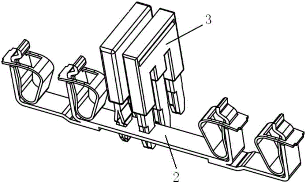
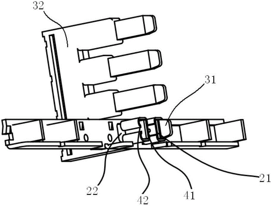
[0026] Such as figure 2 , image 3 , Figure 4 and Figure 5 As shown, a new cross-link connection structure includes a conductive plate 2, a cross-link 3 and a locking elastic piece 4 formed by bending an elastic metal sheet. And the tear hole 22, the cross-link includes a metal pin 31 as a conductive part and an insulating plastic 32 as an operating part; the locking elastic piece includes a side wall 41 and is bent from the same side at both ends of the side wall and then opposite The two elastic clip arms 42 formed by bending and then bending toward the side wall, the locking elastic piece is tightly sleeved on the cantilever, and a jaw is formed between the cantilever and the two elastic clip arms, so The metal pin can be locked and inserted into t...


PUM


Abstract

The invention discloses a new type transverse link connection structure which comprises a current conducting plate, a transverse link and a locking elastic sheet formed when an elastic metal sheet is bent. On the current conducting plate and at the position for the pre-connection of the transverse link are formed a hanging wall and a torn hole. The transverse link comprises a metal pin to serve as a conductive part and an insulation plastic cement to serve as an operation part. The locking elastic sheet comprises two elastic clamping arms formed in such a manner that the side wall and the two ends of the side wall are in the same side, and then bent oppositely from the two ends and then bent again in the same side. The locking elastic sheet is fixed on the hanging wall in an interference fit manner. A clamping port is formed between the hanging arm and the two elastic clamping arms. The metal pin can pass through the torn hole, fastened and inserted into the clamping port. While satisfying the functions, the structure of the invention simplifies a transverse link and resolves the high demand for materials to make a transverse link. In addition, reliable connection can be provided with large contact pressure and smooth plugging. As the contact area between the transverse link and the current conducting plate is large, the requirement for large current can be fulfilled.

Description

technical field [0001] The invention relates to the improvement of the assembly method of accessories in the field of connectors, in particular to a new horizontal connection structure. Background technique [0002] The cross-connection structure means that the plug pins of the cross-connection are electrically connected to the jacks on the conductive plate through their own elastic deformation. When applied, the conductive plate is first assembled on the plastic body of the electrical connector as a conductive connector. The cross-connector is inserted on the plastic body, and the pins of the cross-connector are locked and electrically connected with the jacks on the conductive plate. This kind of cross-connection structure requires the material of the cross-connection pin to have good elasticity and electrical conductivity. Usually, the cross-connection pin is riveted with multiple pieces of copper. See figure 1 , Through the force of lateral dislocation, the connection w...

Claims


Application Information

Patent Timeline
Patent Type & Authority Applications(China)
IPC IPC(8): H01R13/03H01R13/20
CPCH01R13/03H01R13/20
Inventor 邓永其王子建韩广兴梁继栋闫拓
Owner DINKLE M&E CHINA
Learn More