Speed reducer with convenient gear replacement
A technology for reducers and gears, which is applied in the direction of electromechanical devices, mechanical energy control, electrical components, etc., can solve the problems of difficult replacement of reducer gears, difficult maintenance of reducers, and fracture and wear of reduction gears, so as to improve maintenance efficiency and reduce production Cost and maintenance costs, the effect of quick disassembly
- Summary
- Abstract
- Description
- Claims
- Application Information
AI Technical Summary
Problems solved by technology
Method used
Image

Examples
Embodiment 1
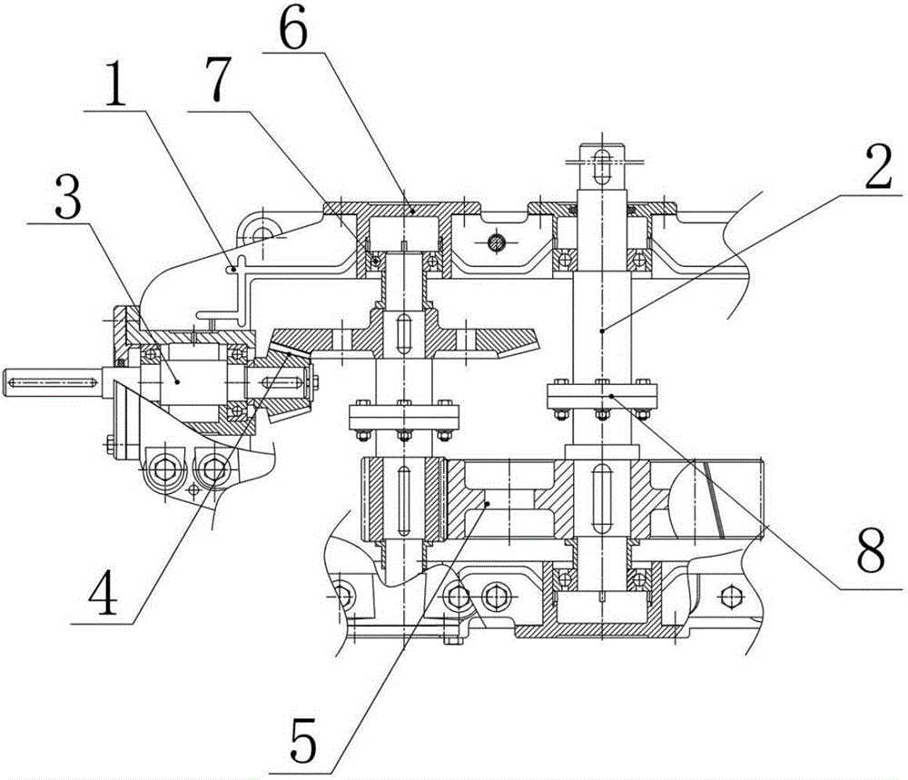
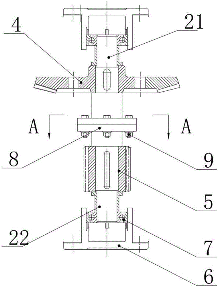
[0016] Example 1: see Figure 1-Figure 3 , A speed reducer that is convenient for gear replacement, including a housing, 1, two drive shafts arranged side by side in the housing 2, an input shaft 3 arranged perpendicular to the drive shaft 2, an input shaft 3 and one of the drive shafts 2 A set of transmission bevel gears 4 between the two transmission shafts, and a set of reduction gears 5 set between the two transmission shafts. The housings at both ends of the transmission shaft are provided with through holes, and the through holes are provided with supports The end cover 6, the outer end of the support end cover 6 and the housing 1 are fixedly connected by bolts, and a support bearing 7 is provided between the inner end of the support end cover 6 and the transmission shaft. The transmission shaft includes a left half shaft 21 and The right half shaft 22, the left half shaft 21 and the right half shaft 22 are all provided with a connecting flange 8 and are fixedly connected...
Embodiment 2
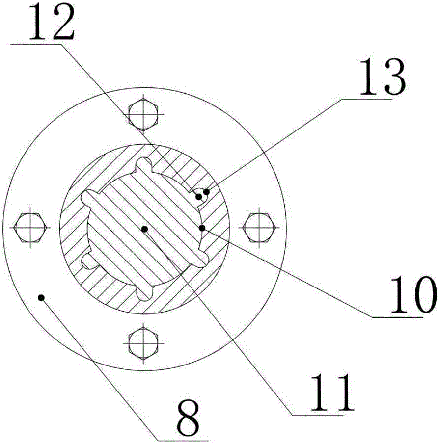
[0017] Embodiment 2: In this embodiment, in order to ensure the effective transmission of the torque of the drive shaft and reduce the shear stress on the bolts, the left half shaft and the right half shaft are respectively provided with matching positioning grooves 10 and positioning posts 11 in the axial direction. The outer wall of the positioning column 11 is provided with a plurality of torque transmission ribs 12 on the circumference, and the inner wall of the positioning groove is provided with a force-bearing groove 13 corresponding to the torque transmission rib.
[0018] The structure of the present invention is reasonable and compact. Through the design of the transmission shaft, the transmission shaft can be effectively split, thereby ensuring that when one of the gears on the same transmission shaft is damaged, it can be quickly disassembled and assembled for timely Replacement greatly reduces the difficulty of maintenance, effectively improves maintenance efficiency,...
PUM
 Abstract
Description
Claims
Application Information