Microfluidic liquid film chiral separation method

A chiral separation and microfluidic technology, applied in the field of membrane separation, can solve problems such as poor stability, product contamination, and reduced efficiency, and achieve the effects of low cost, simple operation, and low dosage

Inactive Publication Date: 2017-09-26
CHANGZHOU UNIV
View PDF5 Cites 0 Cited by
  • Summary
  • Abstract
  • Description
  • Claims
  • Application Information

AI Technical Summary

Problems solved by technology

[0006] A major disadvantage of the liquid film is its poor stability. During long-term operation, the liquid film is easy to gradually dissolve and disperse into the two phases inside and outside the film, resulting in problems such as reduced efficiency and product contamination.

Method used


Image

  • Microfluidic liquid film chiral separation method
  • Microfluidic liquid film chiral separation method

Examples


Embodiment 1

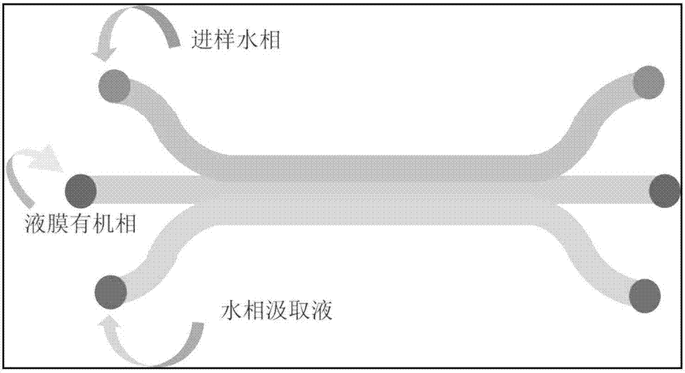
[0023] This embodiment includes the following steps: as shown in the figure 1, (1) prepare a microfluidic liquid membrane separation channel with PDMS polymer material, adopt α-cyclodextrin as chiral selector, its concentration is 0.1mM, Aliquat 336 is used as For the transfer of molecules, diesel oil is used as the organic phase liquid membrane, deionized water is used as the drawing solution, and the concentration of L,D-tryptophan racemate is 0.1mM. At the beginning of the experiment, the flow rate of the middle laminar flow, that is, the diesel liquid film, was controlled to be 5 μL / m, the flow rate of the outer layer of laminar flow, that is, deionized water, was 20 μL / m, and the flow rate of the other outer layer, that is, L, D-tryptophan, was 20 μL / m.

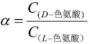
[0024] (2) Determination of the concentration of L-tryptophan and D-tryptophan in the draw solution by liquid chromatography, thereby calculating the size of the chiral separation selectivity coefficient, the test result...

Embodiment 2

[0026] This embodiment includes the following steps: as shown in the figure 1, (1) prepare a microfluidic liquid membrane separation channel with PDMS polymer material, adopt β-cyclodextrin as chiral selector, its concentration is 0.5mM, Aliquat 336 is used as For the transfer of molecules, diesel oil is used as the organic phase liquid membrane, deionized water is used as the drawing solution, and the concentration of L,D-tryptophan racemate is 0.1mM. At the beginning of the experiment, the flow rate of the middle laminar flow, that is, the diesel liquid film, was controlled to be 5 μL / m, the flow rate of the outer layer of laminar flow, that is, deionized water, was 20 μL / m, and the flow rate of the other outer layer, that is, L, D-tryptophan, was 20 μL / m.

[0027] (2) Determination of the concentration of L-tryptophan and D-tryptophan in the drawing solution, thereby calculating the size of the chiral separation selectivity coefficient, the test results are shown in Table 1...

Embodiment 3

[0029] This embodiment includes the following steps: as shown in the figure 1, (1) Prepare a microfluidic liquid membrane separation channel with PDMS polymer material, using γ-cyclodextrin as a chiral selector at a concentration of 0.1mM, and Aliquat336 as a delivery Molecules, diesel oil as the organic phase liquid film, deionized water as the draw solution, the concentration of L, D-tryptophan racemate is 0.1mM. At the beginning of the experiment, the flow rate of the middle laminar flow, that is, the diesel liquid film, was controlled to be 5 μL / m, the flow rate of the outer layer of laminar flow, that is, deionized water, was 20 μL / m, and the flow rate of the other outer layer, that is, L, D-tryptophan, was 20 μL / m.

[0030] (2) Determination of the content of L-tryptophan and D-tryptophan in the drawing solution, thereby calculating the size of the chiral separation selectivity coefficient, the test results are shown in Table 1.


PUM


Abstract

The invention discloses a microfluidic liquid film chiral separation method and relates to a separation method for splitting amino acid racemate. The method comprises the following steps: preparing a microfluidic channel on a PDMS polymerization material, wherein a chiral selective agent and racemate are in a water phase on one side, an organic phase liquid film containing transmitting molecules is in the middle and deionized water on the other side serves as absorbing liquid; splitting the racemate by adjusting the conditions such as the performance and the concentration of the chiral selective agent and the flow quantity of each microfluidic stream. The method is simple in operation and low in energy consumption, the racemate can be split effectively, chiral separation is realized, the use amount of samples and reagents is small, and the cost is reduced.

Description

technical field [0001] The invention belongs to the technical field of membrane separation, and in particular relates to a method for splitting a chiral racemate by a microfluidic liquid membrane. Background technique [0002] The forces that the fluid receives in the microfluidic channel are mainly viscous force (ie, surface force) and pressure (ie, body force). When the surface force plays a leading role, the fluid flow is generally laminar, and the inertial force can be ignored; when the body force plays a leading role, the fluid flow is generally turbulent. In laminar flow, the layers are not mixed with each other, and the movement direction of the particles is parallel to the tube axis; when turbulent flow occurs, the movement of the fluid is chaotic and irregular. The movement state of the fluid can be judged by the Reynolds number. When the Re is far less than 2000, the fluid flow is laminar. In the fluid microfluidic channel designed by the present invention, Re is...

Claims


Application Information

Patent Timeline
IPC IPC(8): B01D11/04C07D209/20
CPCB01D11/0492C07D209/20
Inventor 周政忠
Owner CHANGZHOU UNIV
Why Eureka
Try Eureka