Motor jump ring plugging equipment

A circlip and equipment technology, which is applied in the field of motor circlip insertion equipment, can solve problems such as low efficiency, and achieve high production efficiency, stable insertion quality, and fast insertion and installation

Active Publication Date: 2017-01-18
ZHEJIANG HOUDAR INTELIGENT TECH CO LTD
View PDF6 Cites 0 Cited by
  • Summary
  • Abstract
  • Description
  • Claims
  • Application Information

AI Technical Summary

Problems solved by technology

The circlip used on the motor shaft is an E-shaped circlip (of course, it is also possible to use a U-shaped circlip), and the circlip is provided with a card entrance that is opened by extrusion; in the production process of the motor, it is currently manual Assembling the circlip onto the motor shaft is less efficient

Method used


Image

  • Motor jump ring plugging equipment
  • Motor jump ring plugging equipment
  • Motor jump ring plugging equipment

Examples


Embodiment

[0021] Embodiment: The motor circlip insertion device of the present invention, as attached Figure 10 As shown, it includes a frame 1001, a clip spring device 1002, a motor fine positioning device 1003, a clip spring material distribution device 1004, a visual fixing device 1005, a workpiece tray 1007, a fixed lift positioning stop 1008, and a workpiece from the frame 1001 to Side pass to the workpiece pallet 1009 on the other side.

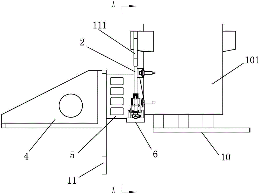
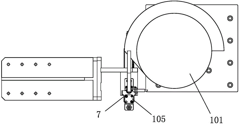
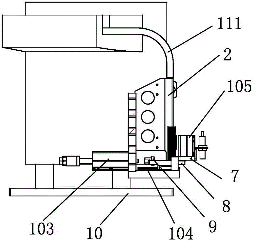
[0022] as attached figure 1 , attached figure 2 , attached image 3 , attached Figure 4 As shown, the circlip dispensing device 1004 comprises a vibrating plate 101, and the vibrating plate 101 has a guide post 111 that guides the motor circlip to move out; the outlet of the guide post 111 is provided with a circlip guide material 2; when the motor circlip is removed from the guide post When moving out on 111, be inserted on the jump ring guide member 2, and stack successively.

[0023] as attached figure 1 , attached figure 2 , attach...


PUM


Abstract

The invention relates to the motor jump ring plugging equipment. The motor jump ring plugging equipment comprises a frame, a jump ring plugging device, a motor fine positioning device, a jump ring feeding device, a visual sense fixing device, a workpiece tray, a lifting positioning blocker and a workpiece tray making a workpiece penetrate from one side of the frame to the other side. Through the motor jump ring plugging equipment, a motor jump ring can be made to realize precise alignment with a motor shaft, rapid plugging mounting is realized, plugging mounting quality is stable, and production efficiency is relatively high.

Description

technical field [0001] The invention relates to an assembly device, in particular to a motor clip spring insertion device. Background technique [0002] The motor circlip is a part on the motor shaft. In mass production, it is necessary to quickly and accurately install the motor circlip on the motor shaft. The two motor shafts often rotate during the assembly process, and it is difficult to accurately and accurately locate them in the circumferential direction; patented in China A motor is disclosed in the patent document with the publication number CN104539078 and the name "Permanent Magnet Brushless Motor with Dust Structure on the Rotor". In order to prevent axial displacement of the parts connected to the motor shaft, a circlip is installed on the motor shaft, and a positioning plane is provided on the peripheral surface of the end of the motor shaft provided with the circlip groove. The circlip used on the motor shaft is an E-shaped circlip (of course, it is also poss...

Claims


Application Information

Patent Timeline
Patent Type & Authority Applications(China)
IPC IPC(8): H02K15/00
CPCH02K15/00
Inventor 蔡永潮陈敬生何永全方勇
Owner ZHEJIANG HOUDAR INTELIGENT TECH CO LTD
Why Eureka
Try Eureka