Fixed camera calibration method

A technology of fixing camera and calibration method, applied in electrical components, printed circuit manufacturing, electrical components, etc., can solve problems such as large errors, and achieve the effect of improving accuracy and improving placement effect

Active Publication Date: 2017-01-18
HARBIN INST OF TECH
View PDF5 Cites 9 Cited by
  • Summary
  • Abstract
  • Description
  • Claims
  • Application Information

AI Technical Summary

Problems solved by technology

[0004] In order to overcome the technical deficiencies of the manual mechanical installation of the fixed camera of the existing placement machine, which cannot avoid the deviation cause

Method used


Image

  • Fixed camera calibration method
  • Fixed camera calibration method
  • Fixed camera calibration method

Examples


specific Embodiment approach 1

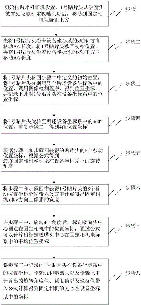
[0042] A method for calibrating a fixed camera in this embodiment is implemented through the following steps:

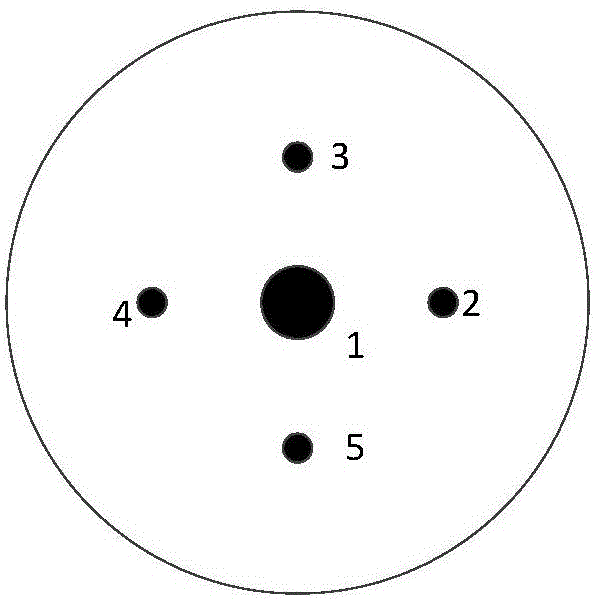
[0043]Step 1: Initialize the camera settings of the placement machine, set the moving length A of the placement head when the fixed camera is calibrated, the unit is mm, after the No. 1 placement head sucks the calibration nozzle head from the ANC nozzle head slot, moves to the fixed camera field of view. Just above, calibrate The target is to calibrate the nozzle tip; ANC stands for the nozzle tip groove.

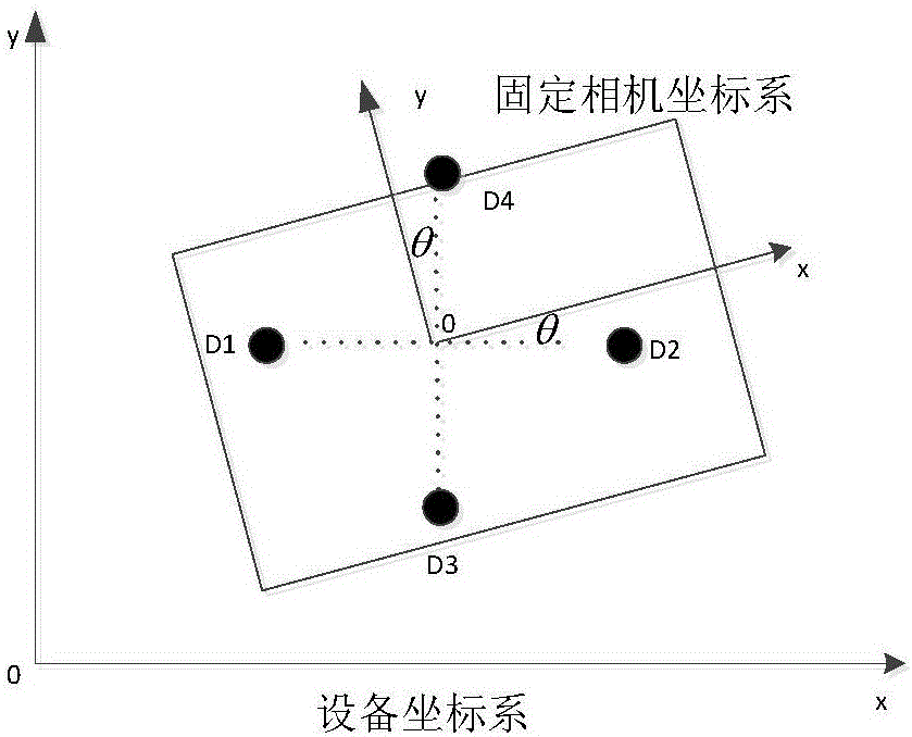
[0044] Step 2: Set the position of the No. 1 patch head in the device coordinate system as the initial position at this moment, first move the No. 1 patch head along the negative direction of the x-axis of the device coordinate system by A / 2 length, and then call the image detection program to get Calibrate the position coordinates of the center of the nozzle head in the fixed camera, marked as D1(x 1 ,y 1 ); then move the No. 1 placement head back to the initi...

specific Embodiment approach 2

[0062] Different from the specific embodiment one, step one is specifically:

[0063] Step 11: Click the function button used for patching the fixed camera, and read the moving length A of the fixed camera according to the prompts on the image interface;

[0064] Step 1 and 2: Place all nozzles according to the prompts on the graphical interface;

[0065] Step 1 and 3: Control the hardware to obtain the calibration nozzle head from the place where the nozzle head is placed, and move the No. 1 placement head to the position of the fixed camera center field of view according to the graphical interface prompt of the placement machine;

[0066] Step 14: Control the No. 1 placement head to move above the center of the fixed camera.

[0067] The specific operation of this embodiment can be as follows:

[0068] 1) Click the button in the placement machine to prompt to place the nozzle. Read the moving length of the fixed camera from the "Fixed Camera" control in the "Moving Lengt...

specific Embodiment approach 3

[0074] Different from the specific embodiment one or two, step two is specifically:

[0075] Step 21: Move the No. 1 patch head along the x-axis by -A / 2, and set the coordinates of the No. 1 patch head relative to the fixed camera optical center at this time as D(x,y)=(-A / 2,0), unit mm;

[0076] Step 22: Input the image captured by the fixed camera at this time into the image detection program to obtain the position D of the center point of the calibration nozzle head in the fixed camera 1 (x 1 ,y 1 ), the unit is pixel;

[0077] Step 23: Move the No. 1 patch head along the x-axis by A. At this time, the coordinate of the No. 1 patch head relative to the optical center of the fixed camera is (A / 2,0), and the image captured by the fixed camera at this time is input to the image detection Program to get the position D of the center of the circle in the fixed camera 2 (x 2 ,y 2 ), unit pixel;

[0078] Step 24: Move the No. 1 patch head along the x-axis by -A / 2, and move a...


PUM


Abstract

The invention discloses a fixed camera correction method, belongs to the machine vision localization detection field and is applied to the high-accuracy correction process of a surface mounting machine. The main objective of the invention is to solve the problem that the location, scale and rotation angle of the fixed camera of an existing surface mounting machine cannot be accurately measured in an equipment coordinate system when the fixed camera of the surface mounting machine is mechanically installed. According to the method of the invention, the positional relationship of a surface mounting head in a fixed camera is determined according to a calibration suction nozzle; a conversion relation between two coordinate systems is calculated and derived; the scale of the fixed camera is calculated through the position coordinates of a center; and the rotation angle of the fixed camera in an equipment coordinate system is calculated according to the position coordinates of the surface mounting head and the value coordinates of the surface mounting head. The coordinates, the rotation angle and the scale of the fixed camera are corrected, so that deviation in a detection process caused by manual installation can be offset, the calibration point detection and positioning accuracy of the surface mounting machine can be improved, and the surface mounting effect of the surface mounting machine can be improved. The fixed camera correction method of the invention is suitable for the machine vision precision correction field.

Description

technical field [0001] The invention relates to a fixed camera calibration method, belonging to the technical field of machine vision positioning detection. [0002] technical background [0003] In the SMT placement machine, the fixed camera is fixedly mounted on the immovable fixed frame. During the SMT production process, the position, scale and rotation angle of the fixed camera must be accurately obtained first, so that the system zero point, the origin coordinate system of the reference camera and other related information can be accurately found later. The accurate measurement of parameters such as the position, scale and rotation angle of the fixed camera determines whether the coordinate system of the entire placement machine system can be accurately constructed, which affects the positioning accuracy of the SMD chip during the placement production process. When the fixed camera of the existing placement machine is installed manually, the deviation caused by manual ...

Claims


Application Information

Patent Timeline
IPC IPC(8): H05K3/30H05K13/08
CPCH05K3/303H05K13/08H05K2203/166
Inventor 高会军许超刘鑫杨宪强孙昊白立飞张智浩
Owner HARBIN INST OF TECH
Why Eureka
Try Eureka