A Laser Gyroscope Based on Longitudinal Radio Frequency Discharge
A technology of radio frequency discharge and laser gyro, which is applied in the field of laser gyro, can solve the problems of low discharge efficiency, serious electromagnetic radiation, complex structure, etc., and achieve the effect of high discharge efficiency, small size and simple structure
Active Publication Date: 2014-12-03
FLIGHT AUTOMATIC CONTROL RES INST
View PDF0 Cites 3 Cited by
- Summary
- Abstract
- Description
- Claims
- Application Information
AI Technical Summary
Problems solved by technology
The structure of this technical scheme is complex, and it is necessary to add a winding groove of the solenoid and a conductor with good performance on the outer wall of the discharge channel. At the same time, due to the problem of electromagnetic conversion, the discharge efficiency is low and the electromagnetic radiation is serious.
Method used
View moreImage
Smart ImageViewing Examples
Examples
Embodiment Construction
Login to View More PUM
 Abstract
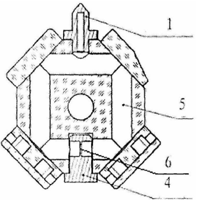
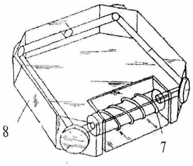
The invention belongs to laser gyroscope technology, and relates to a laser gyroscope based on longitudinal radio frequency discharge. The laser gyroscope based on longitudinal radio frequency discharge includes a cavity, a reflector, a charging and exhausting electrode, and an aperture electrode, wherein, interconnected annular capillary holes are arranged in the cavity, and the charging and discharging electrodes are metal tubes , is arranged on the cavity and communicates with the annular capillary hole, and the diaphragm electrode is arranged opposite to the charging and exhausting electrode, and the central axes of the two are consistent. In addition, a section of the diaphragm electrode communicates with the annular capillary hole, and the aperture The small radial through hole acts as a stop to ensure the normal operation of the laser gyro in the fundamental transverse mode. The laser gyro based on longitudinal radio frequency discharge of the present invention provides laser gain by high voltage and low frequency radio frequency discharge, has small volume, simple structure, high discharge efficiency, and small electromagnetic radiation, effectively realizing the miniaturization of the laser gyro.
Description
A Laser Gyro Based on Longitudinal Radio Frequency Discharge technical field The utility model belongs to the laser gyroscope technology and relates to a laser gyroscope based on longitudinal radio frequency discharge. Background technique Laser gyro is a kind of angular velocity sensor, which generally adopts a ring laser, and its gain method often adopts a high-voltage DC discharge method. Miniaturization is a development trend of optical gyroscopes. However, when the cavity length of laser gyroscopes becomes smaller, the conventional DC discharge method is difficult to meet the gain requirements, and DC discharge will cause output errors of laser gyroscopes. In addition, key components such as diaphragms and light combining devices commonly used in laser gyroscopes require high processing and installation tolerances and high costs, making it difficult to meet the application requirements of micro-miniature laser gyroscopes with cavity lengths within 40mm. The existing...
Claims
Login to View More Application Information
Patent Timeline
 Patent Type & Authority Patents(China)
IPC IPC(8): G01C19/64
Inventor 王维科刘元正严吉中叶萍兰佩峰胡强
Owner FLIGHT AUTOMATIC CONTROL RES INST
Features
- R&D
- Intellectual Property
- Life Sciences
- Materials
- Tech Scout
- Unparalleled Data Quality
- Higher Quality Content
- 60% Fewer Hallucinations
Learn More Browse by: Latest US Patents, China's latest patents, Technical Efficacy Thesaurus, Application Domain, Technology Topic, Popular Technical Reports.
© 2025 PatSnap. All rights reserved.Legal|Privacy policy|Modern Slavery Act Transparency Statement|Sitemap|About US| Contact US: help@patsnap.com


