

A ground-based ionospheric network monitoring method
An ionospheric and ionospheric reflection technology, applied in electrical components, radio transmission systems, electrical digital data processing, etc., can solve problems such as low horizontal spatial resolution and inability to meet high-resolution ionospheric monitoring, and achieve fast construction period , The effect of low construction cost
Inactive Publication Date: 2013-12-04
THE 22ND RES INST OF CHINA ELECTRONICS TECH GROUP CORP
View PDF0 Cites 2 Cited by
- Summary
- Abstract
- Description
- Claims
- Application Information
AI Technical Summary
Problems solved by technology
In summary, the current ground-based ionospheric monitoring technology in my country has the obvious deficiency of low horizontal spatial resolution, which cannot meet the needs of various aspects for high-resolution ionospheric monitoring. There is an urgent need to develop ground-based ionospheric high-resolution monitoring technology
Method used
View moreImage
Smart ImageViewing Examples

Examples
no. 1 example
Login to View More PUM
 Abstract
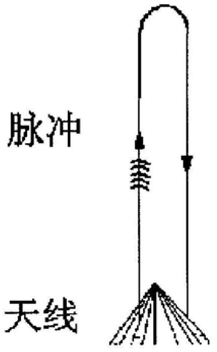
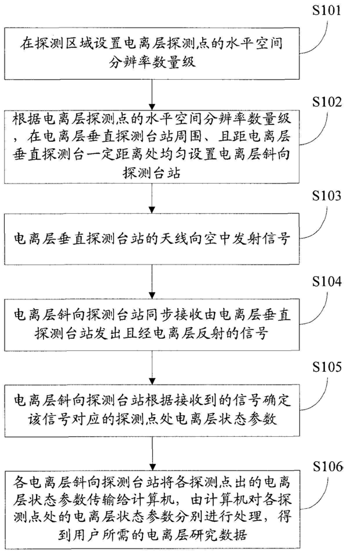
The invention discloses a ground-based ionospheric network monitoring method, comprising: setting the order of magnitude of horizontal spatial resolution of ionospheric detection points in the detection area; The ionospheric oblique detection stations are uniformly set at a certain distance around the station; each ionospheric detection point is located in the middle of the ionospheric vertical detection station and the ionospheric oblique detection station; The ionospheric vertical detection station sends out the signal and is reflected by the ionosphere to determine the ionospheric state parameters at each ionospheric detection point. The invention can realize the high-resolution monitoring of the ionospheric foundation in the concerned detection area by rationally arranging a plurality of ionospheric oblique detectors. Since the ionospheric oblique sounder is used as the main monitoring method, it will not have adverse effects on the human body and radio equipment, and can provide more ionospheric information.
Description
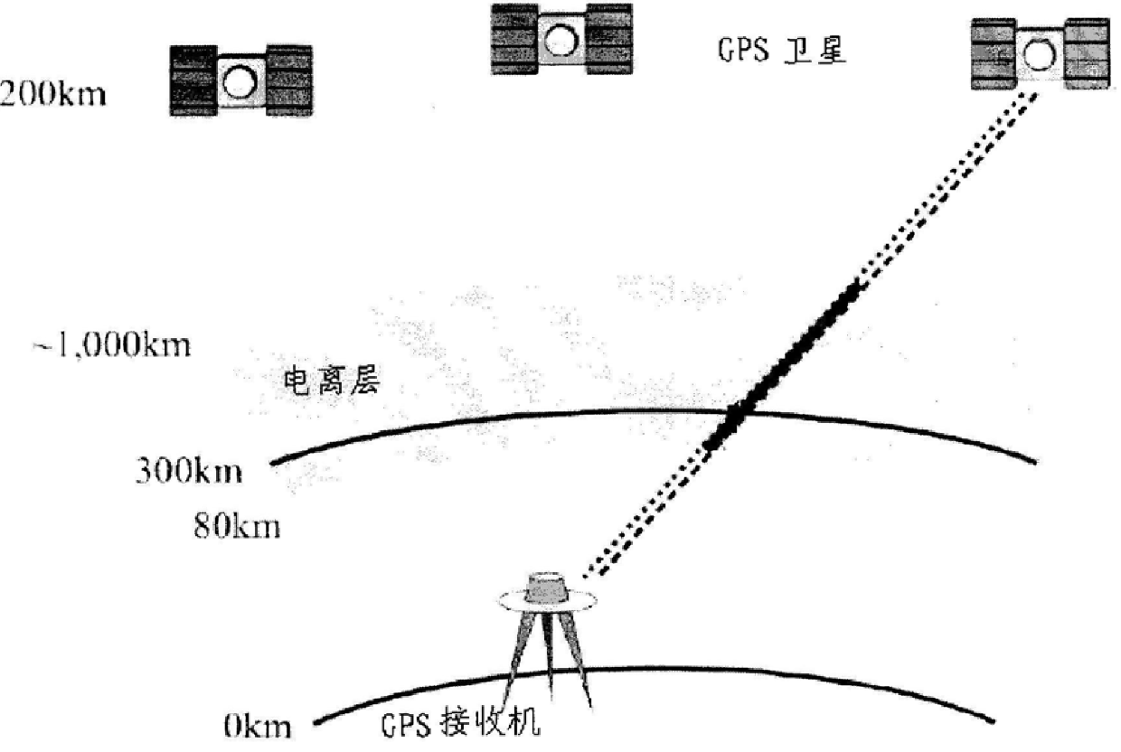
A ground-based ionospheric network monitoring method technical field The invention relates to the technical field of space environment monitoring, in particular to a ground-based ionospheric network monitoring method. Background technique The ionosphere is a space region above 60 kilometers to about 1000 kilometers above the ground, where there are a large number of free electrons, which have an important impact on the propagation characteristics of radio signals, and are an important content of various radio systems. For example, the short-wave long-distance communication system is realized by the reflection of the ionosphere to the short-wave signal, and the electron density distribution of the ionosphere directly determines the available frequency band of the short-wave communication link. In a relatively stable state, the ionosphere has a good horizontal spatial correlation within a range of about 500 kilometers, that is, the ionosphere changes little within a horizon...
Claims
Login to View More Application Information
Patent Timeline
 Patent Type & Authority Patents(China)
IPC IPC(8): G06F19/00H04B7/00
Inventor 吴健黄昌理丁宗华许正文赵振维李安民刘玉梅
Owner THE 22ND RES INST OF CHINA ELECTRONICS TECH GROUP CORP