Movable bone traction device

A technology of bone traction and splint fixation, applied in medical science, external fixator, surgery, etc., can solve problems such as decubitus ulcer, deep vein thrombosis, joint stiffness, etc., achieve the effect of reducing production cost, convenient operation, and avoiding decubitus ulcer

Inactive Publication Date: 2017-01-25
WEST CHINA HOSPITAL SICHUAN UNIV
View PDF4 Cites 6 Cited by
  • Summary
  • Abstract
  • Description
  • Claims
  • Application Information

AI Technical Summary

Problems solved by technology

However, the use of traditional bone traction devices requires the patient to lie flat on the hospital bed for a long time to maintain the stability of the fracture traction. Since the patient cannot move the body for a long time, it is easy to cause bedsores, deep vein thrombosis, and even lung infection in severe cases. , muscle atrophy, joint stiffness and other complications

Method used


Image

  • Movable bone traction device
  • Movable bone traction device
  • Movable bone traction device

Examples


Embodiment 1

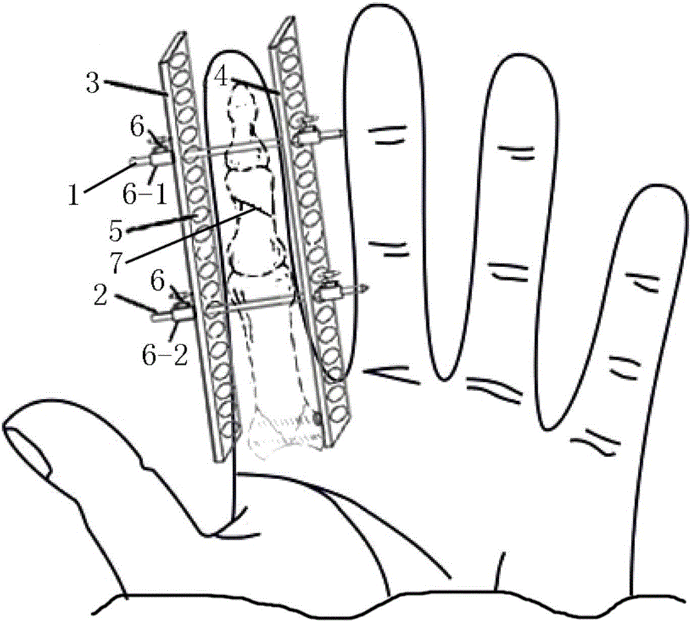
[0024] Patient is finger fracture in the present embodiment.

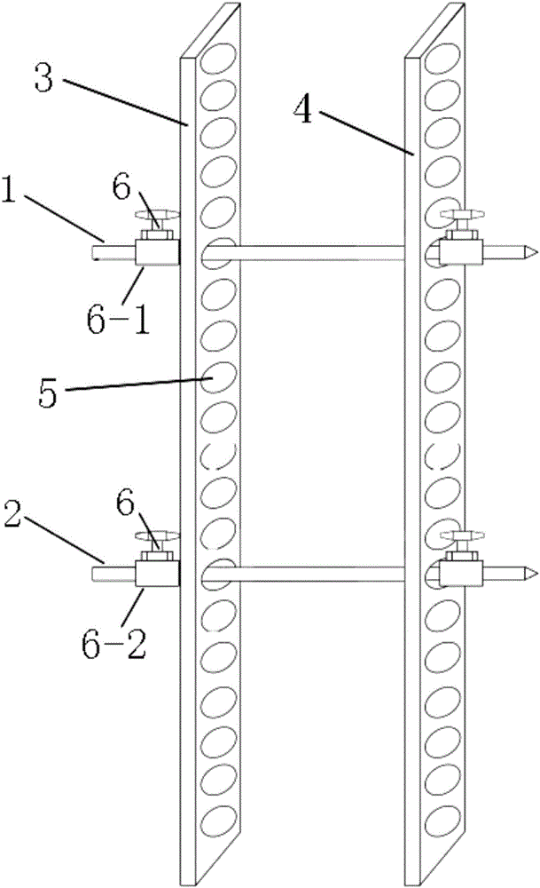
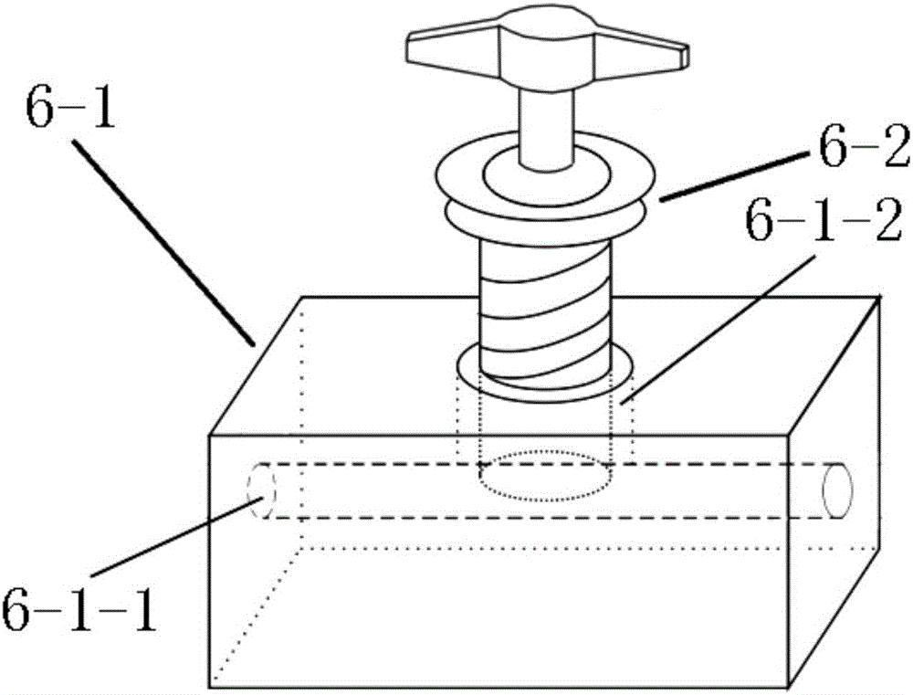
[0025] The movable bone traction device provided by this embodiment is as figure 1 As shown, including Kirschner wires, fixing splints and limit mechanism 6, the Kirschner wires are two, respectively named as the first Kirschner wires 1 and the second Kirschner wires 2, and the fixing splints are two, They are respectively named as the first fixed splint 3 and the second fixed splint 4, and the number of the limiting mechanisms 6 is four.

[0026] The length, width and thickness of the first fixed splint 3 and the second fixed splint 4 are equal, and the length is 3cm, the width is 1cm, and the thickness is 0.3cm. On the first fixed splint 3 and the second fixed splint 4 All are provided with a plurality of Kirschner wire support holes 5, and a plurality of Kirschner wire support holes 5 are arranged in a row along the length direction of the first fixed splint 3 and the second fixed splint 4 respectively, and the...

Embodiment 2

[0030] In the present embodiment, the patient is a fracture of the tibia and fibula of the lower extremity.

[0031] The movable bone traction device provided by this embodiment is as figure 1 As shown, including Kirschner wires, fixing splints and limit mechanism 6, the Kirschner wires are two, respectively named as the first Kirschner wires 1 and the second Kirschner wires 2, and the fixing splints are two, They are respectively named as the first fixed splint 3 and the second fixed splint 4, and the number of the limiting mechanisms 6 is four.

[0032] The length, width and thickness of the first fixed splint 3 and the second fixed splint 4 are equal, and the length is 100cm, the width is 15cm, and the thickness is 1cm. Both the first fixed splint 3 and the second fixed splint 4 A plurality of Kirschner wire support holes 5 are provided, and the plurality of Kirschner wire support holes 5 are arranged in a row along the length direction of the first fixed splint 3 and the ...


PUM


Abstract

The invention provides a movable bone traction device. The movable bone traction device comprises Kirschner wires, fixed clamping plates and limiting mechanisms; the two Kirschner wires are arranged and are named as a first Kirschner wire and a second Kirschner wire respectively; the two fixed clamping plates are arranged and are named as a first fixed clamping plate and a second fixed clamping plate respectively; a plurality of Kirschner wire supporting holes are formed in the first fixed clamping plate and the second fixed clamping plate; the four limiting mechanisms are arranged. When the movable bone traction device is used, the two ends of the first Kirschner wire and the second Kirschner wire penetrate through the Kirschner wire supporting holes formed in the first fixed clamping plate and the second fixed clamping plate respectively to stretch out; the four limiting mechanisms are arranged at two ends of the first Kirschner wire and the second Kirschner wire respectively, and are in contact with outer side surfaces of the first fixed clamping plate and the second fixed clamping plate respectively. By adopting the device provided by the invention, the aim of fracture traction and stretching can be realized, and a patient can more freely to a certain extent; complications of bedsores, deep venous thrombosis and the like, caused by the fact that the patient lies on a sickbed for long time, are avoided, and the treatment effect is improved.

Description

technical field [0001] The invention belongs to the field of bone traction devices, in particular to a movable bone traction device. Background technique [0002] In clinical medicine, fracture traction is a relatively common treatment method for extremity fractures. Bone traction can overcome muscle contraction, stretch the fracture ends, prevent and correct soft tissue contracture, and maintain the relative position of the fracture ends, stabilizing Fractures can reduce pain for patients, protect surrounding tissues, create conditions for surgery, and can be used as the final treatment for fractures under certain conditions. [0003] Traditional bone traction devices mainly include Kirschner wires, traction bed frames, traction brackets, traction accessories (three-step ladder, three-height bed pad, backrest frame, foot pedal box, traction bow) and the like. The operation steps of using the traditional bone traction device for bone traction are as follows: 1. Place the pa...

Claims


Application Information

Patent Timeline
Patent Type & Authority Applications(China)
IPC IPC(8): A61B17/66
CPCA61B17/66A61B17/6425A61B2017/564
Inventor 项舟段鑫龙也
Owner WEST CHINA HOSPITAL SICHUAN UNIV
Why Eureka
Try Eureka