Lumbar cervical stretcher

A stretcher, lumbar and cervical spine technology, applied in passive exercise equipment, medical science, non-surgical orthopedic surgery, etc., can solve the problems of being unsuitable for home use, large limitations, and the need for a stool to occupy indoor space, so as to achieve easy operation , the effect of simple structure

Active Publication Date: 2017-01-25
蒋息娟
View PDF7 Cites 3 Cited by
  • Summary
  • Abstract
  • Description
  • Claims
  • Application Information

AI Technical Summary

Problems solved by technology

The desktop type is large in size and complex in structure. The traction is controlled by electric motors and has complete functions. However, it is mainly suitable for hospital treatment and is not suitable for home use. The stool type has a complicated structure, and the traction device is installed under the stool. It is inconvenient for the user to stretch and unlock it. Stools need to occupy indoor space and affect the appearance of the room; the hanging structure is simple, but it needs to provide hanging objects, which is inconvenient to use and unsightly, with great limitations

Method used


Image

  • Lumbar cervical stretcher
  • Lumbar cervical stretcher
  • Lumbar cervical stretcher

Examples


Embodiment 1

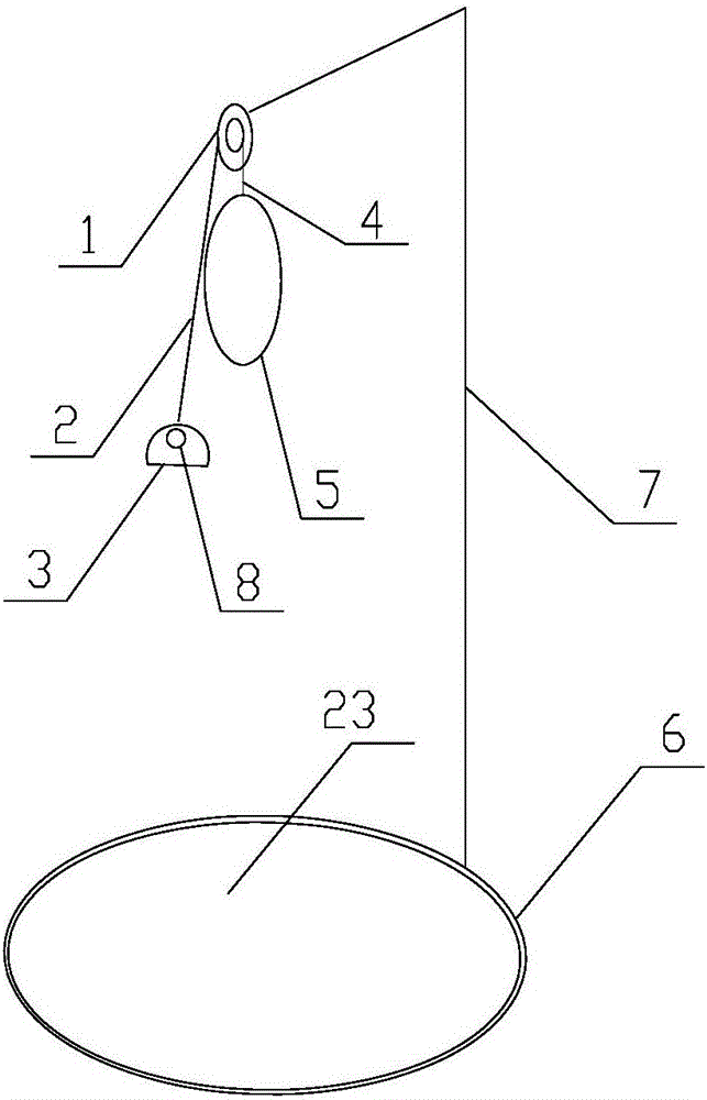
[0026] Such as figure 1 As shown, the lumbar and cervical stretcher in Embodiment 1 is mainly composed of a pulling device, a locking device and a suspension device for installing the pulling device.

[0027] Such as figure 1 As shown, in the present embodiment 1, the suspension device is mainly composed of a single rod support 7 and a base 6, the upper end of the single rod support 7 is used to install a pulling device, and the lower end of the single rod support 7 is fixed on the base 6; A rotatable seat cushion 23 is arranged inside the seat 6, and the direction of the user can be adjusted by rotating the seat cushion 23 during use.

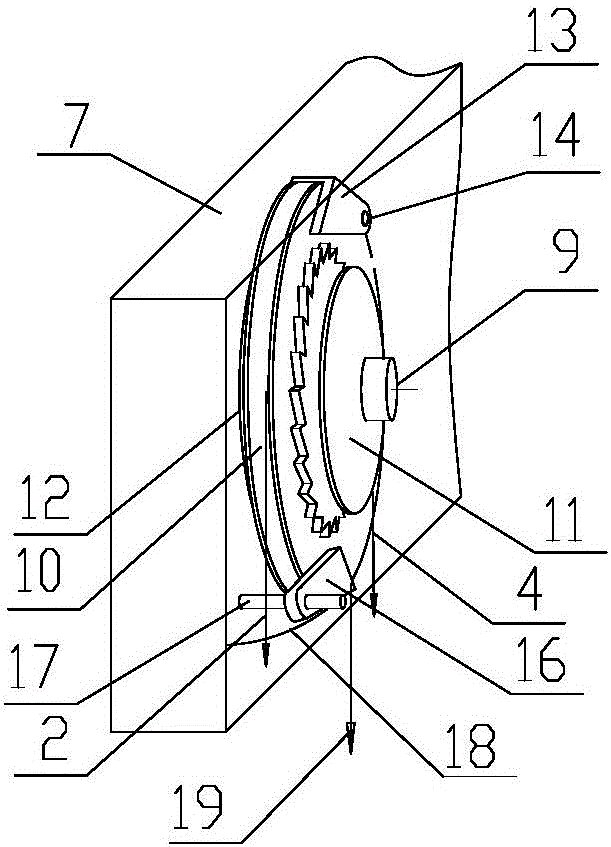
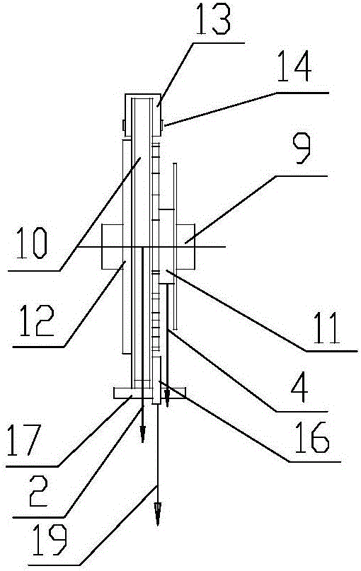
[0028] Such as Figure 1~Figure 4 As shown, in the present embodiment 1, the pulling device is mainly composed of a speed change wheel 1, a hand rope 2, a hand pull ring 3, a traction rope 4 and a neck sleeve 5, and the speed change wheel 1 is installed on a fixed shaft 9 , both ends of the fixed shaft 9 are supported and installed on the s...

Embodiment 2

[0033] Such as Figure 5As shown, the lumbar and cervical stretcher in Embodiment 2 mainly consists of a pulling device, a locking device and a suspension device for installing the pulling device.

[0034] Such as Figure 5 As shown, the difference between this embodiment 2 and embodiment 1 is that the suspension device is different. The suspension device of embodiment 2 is mainly composed of a single rod bracket 7 and a chair back hook 20. The upper end of the single rod bracket 7 is used to install a pulling device , the back of the single-bar support 7 is provided with a chair back hook 20, and the chair back hook 20 is fixed on the seat back during use to realize the fixing of the suspension device.

[0035] The difference between this embodiment 2 and embodiment 1 lies in the use of different carriers. The lumbar and cervical spine stretcher of embodiment 1 is placed arbitrarily on flat surfaces such as sofas, stools, tatami mats, and beds. The lumbar and cervical spine ...

Embodiment 3

[0039] Such as Image 6 As shown, the lumbar and cervical stretcher in Embodiment 3 mainly consists of a pulling device, a locking device and a suspension device for installing the pulling device.

[0040] Such as Image 6 As shown, the difference between Embodiment 3 and Embodiment 1 is that the suspension device is different. The suspension device in Embodiment 3 is a double-bar support 21, and the bottom of the double-bar support 21 is provided with a base 6 to keep the suspension device stable; the base 6 A rotatable seat cushion 23 is arranged inside, and the orientation of the user can be adjusted by rotating the rotatable seat cushion 23 during use.

[0041] The difference between embodiment 3 and embodiment 1 is that the setting positions of the pull ring 3 and the unlocking ring 8 are different. The rope 2 and the unlocking pull cord 19 are concealedly arranged in the double-bar bracket 21 .

[0042] The structures and usage methods of the pulling device and the lo...


PUM


Abstract

The invention relates to a lumbar cervical stretcher, which comprises a traction device, a locking device and a hanging device, wherein a speed change wheel arranged in the traction device is arranged on a fixing shaft; the two ends of the fixing shaft are arranged on the hanging device; the speed change wheel comprises a big wheel, a small wheel with ratchets and a reset spring; the big wheel, the small wheel with the ratchets and the reset spring are in coaxial arrangement; rope grooves are formed in the peripheral surfaces of the big wheel and the small wheel with the ratchets; a hand pulling rope is wound in the rope groove of the big wheel; one end of the hand pulling rope is connected with the big wheel; the other end of the hand pulling rope is connected with a hand pulling ring; the traction rope is wound in the rope groove of the small wheel with the ratchets; one end of the traction rope is connected with the small wheel with the ratchets; the other end of the traction rope is connected with a neck sleeve; the reset spring is arranged on the fixing shaft; one end of the reset spring is connected with the big wheel; the other end of the reset spring is connected with the fixing shaft; the reset spring is used for automatically resetting when the big wheel does not receive the pulling force of the hand pulling rope. The lumbar cervical stretcher is applicable to home use and various occasions; the lumbar cervical stretcher can be collected when being not used; the indoor space is not occupied; the operation is convenient and safe; a user can regulate the traction force intensity.

Description

technical field [0001] The invention relates to a medical and health care device, in particular to a lumbar and cervical stretcher. Background technique [0002] At present, pain and discomfort in the waist and cervical spine have become a common symptom that plagues people. It not only occurs widely in middle-aged and elderly people, but also due to the increased pressure of work and study in modern people, lack of good living habits in daily life, or failure to form correct health care Common sense and concepts, so the incidence among young and middle-aged people is also increasing year by year. With the improvement of people's living standards and the widespread popularization of the national fitness craze under the advocacy of the Olympic concept, lumbar and cervical spine discomfort symptoms have become one of the focus topics that people generally pay attention to in the process of pursuing a healthy body. [0003] Prevention of cervical and lumbar spondylosis is the ...

Claims


Application Information

Patent Timeline
Patent Type & Authority Applications(China)
IPC IPC(8): A61F5/042A61F5/045A61H1/02
CPCA61F5/0104A61F5/042A61H1/0218A61H1/0292A61H1/0296A61H2201/0142A61H2201/0149A61H2201/1253A61H2205/04A61H2205/08
Inventor 缪卫良蒋息娟
Owner 蒋息娟
Why Eureka
Try Eureka