Convenient-to-clean anti-noise high-stirring-force chemical reaction tank

A chemical reaction and stirring force technology, which is applied in chemical/physical/physical chemical fixed reactors, mixer accessories, mixers with rotating stirring devices, etc., can solve problems affecting work efficiency, loud vibration, slow response, etc. , to achieve the effect of speeding up the reaction speed, reducing noise and efficient stirring

Inactive Publication Date: 2017-01-25
ZHENGZHOU SOUQU INFORMATION TECH CO LTD
4 Cites 10 Cited by

AI-Extracted Technical Summary

Problems solved by technology

[0002] At present, there is an existing chemical reaction tank, which includes a tank body and a tank cover. The tank body and the tank cover are connected by flanges. The tank body is provided with a stirring shaft, and the stirring shaft is provided with a stirring paddle. The shafts are connected. The chemical reaction tank with this structure is unstable during use, the vibration sound is loud, and the material cannot be discharged quickly, which w...

Abstract

The invention provides a convenient-to-clean anti-noise high-stirring-force chemical reaction tank, which comprises a reaction tank, wherein an upper cover is arranged in the top opening position of the reaction tank; a feeding pipe and a cleaning device are arranged on the upper cover; the cleaning device is arranged in the middle part of the upper cover, and consists of a transmission box, a rotating motor and a rotating spraying disc; the inside of the reaction tank is separated into a reaction cavity and a transmission cavity through a separation plate; a stirring device is arranged in the reaction cavity, and consists of a first stirrer, a second stirrer and a third stirrer; a cooling water pipe is embedded in the side wall of the reaction tank; the cooling water pipe is in coiled arrangement; the two ends of the cooling water pipe are connected with a connecting pipe; a water pump and a cooling tank are arranged on the connecting pipe. Through the arrangement of the cleaning device, the used reaction tank can be cleaned, and the use in the next time is convenient; through the arrangement of the stirring device, chemical engineering materials are sufficiently stirred; a spiral auger is arranged in the middle part of the first stirring shaft, so that materials near the first stirring shaft are stirred.

Application Domain

Technology Topic

Water pipeChemical reaction +1

Image

  • Convenient-to-clean anti-noise high-stirring-force chemical reaction tank
  • Convenient-to-clean anti-noise high-stirring-force chemical reaction tank
  • Convenient-to-clean anti-noise high-stirring-force chemical reaction tank

Examples

  • Experimental program(1)

Example Embodiment

[0016] The technical solution of the present patent will be described in further detail below in conjunction with specific embodiments.
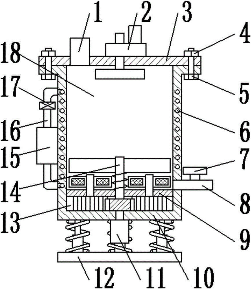
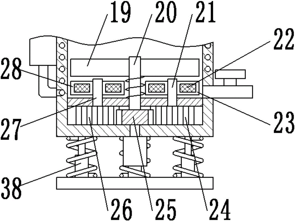
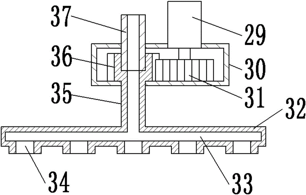
[0017] see Figure 1-4 , a noise-proof chemical reaction tank with high stirring force that is easy to clean, including a reaction tank 10; the reaction tank 10 is arranged as a cylinder, and an upper cover 3 is provided at the top opening; the upper cover 3 is provided with bolts 5 and nuts. 4 is fixedly connected with the reaction tank 10 by mutual screwing; the upper cover 3 is provided with a feeding pipe 1 and a cleaning device 2; The cleaning device 2 is arranged in the middle of the upper cover 3 and consists of a transmission box 30, a rotating motor 29 and a rotating spray plate 32; the transmission box 30 is provided with a fourth gear 31 and a fifth gear 36; the fourth gear 31 It is fixedly connected with the main shaft of the rotary motor 29; the rotary motor 29 is fixed on the upper surface of the transmission box 30 to provide rotary power; the fifth gear 36 and the fourth gear 31 are meshed with each other, and the top of the fifth gear 36 is connected to the input The water pipe 37 is movably connected, and the bottom is fixedly connected with one end of the conduit 35; the water inlet pipe 37 is fixedly connected with the transmission box 30 for introducing clean water; the other end of the conduit 35 is fixedly connected with the rotating spray disc 32; the rotating The spray disc 32 is arranged in a disc shape, and a number of nozzles 34 are evenly arranged on the lower surface; the fifth gear 36, the conduit 35 and the inside of the rotating spray disc 32 are provided with a flow channel 33; the cleaning device 2 is provided for cleaning after use. The inside of the reaction tank 10 is divided into a reaction chamber 18 and a transmission chamber 13 by the partition 9; the reaction chamber 18 is provided with a stirring device 14; the stirring device 14 is composed of a first A stirrer, a second stirrer and a third stirrer are formed; the first stirrer is composed of a first stirring blade 19 and a first stirring shaft 20; the first stirring blade 19 is provided with two pieces, which are fixed on the first stirring blade 19 The top of the stirring shaft 20; the middle part of the first stirring shaft 20 is provided with a spiral auger for stirring the materials near the first stirring shaft 20; the second stirrer is composed of the second stirring blade 28 and the second stirring shaft 27; the second stirring blade 28 is provided with two pieces, which are fixed on the top of the second stirring shaft 27; the third stirring blade is composed of the third stirring blade 23 and the third stirring shaft 21; the third stirring blade 23 is provided with two pieces, which are fixed on the top of the third stirring shaft 21; the surfaces of the second stirring piece 28 and the third stirring piece 23 are provided with an electric heating net 22; reaction, the setting of the electric heating net 22 is convenient for heating the reverse direction that needs to be heated, and further accelerates the reaction speed; the transmission cavity 13 is provided with a first gear 25, a second gear 26 and a third gear 24; the first gear 25, the second gear 26 and the third gear 24 The gear 25 is arranged in the middle of the transmission cavity 13, the upper surface is fixedly connected with the bottom of the first stirring shaft 20, and the lower surface is fixedly connected with the main shaft of the drive motor 11; the drive motor 11 is fixed on the lower surface of the reaction tank 10; the second gear 26 meshes with the first gear 25, and the upper surface of the second gear 26 is fixedly connected to the bottom of the second stirring shaft 27; the third gear 24 meshes with the first gear 25, and the upper surface of the third gear 24 Three stirring shafts The bottom of 21 is fixedly connected; the gear in the transmission cavity 13 is driven by the driving motor 11 to rotate, and the gear drives the stirring device 14 to rotate, so as to achieve the purpose of efficient stirring; the cooling water pipe 6 is embedded in the side wall of the reaction tank 10; the cooling water pipe 6 It is arranged in a spiral, and both ends are connected with the connecting pipe 16; the connecting pipe 16 is provided with a water pump 17 and a cooling tank 15; the cooled water is circulated through the water pump 17 to cool the reaction tank 10, which is convenient for the heat-producing reaction. Ensure that the reaction is carried out safely; the side wall of the reaction tank 10 is provided with a discharge pipe 8; the discharge pipe 8 is provided with a discharge valve 7; The shock device 38 is composed of a spring 39, a guide sleeve 40 and a guide post 41; the spring 39 is arranged on the outer surfaces of the guide sleeve 40 and the guide post 41; the bottom of the guide sleeve 40 is fixedly connected to the bottom plate 12; the guide post 41 is provided In the guide sleeve 40, and the top of the guide post 41 is fixedly connected with the bottom surface of the reaction tank 10; the damping device 38 is provided to absorb the vibration generated during the stirring process and reduce the noise.
[0018] The preferred embodiments of the present patent have been described in detail above, but the present patent is not limited to the above-mentioned embodiments. Within the scope of knowledge possessed by those of ordinary skill in the art, the present invention can also be made without departing from the purpose of the present patent. Various changes.

PUM

no PUM

Description & Claims & Application Information

We can also present the details of the Description, Claims and Application information to help users get a comprehensive understanding of the technical details of the patent, such as background art, summary of invention, brief description of drawings, description of embodiments, and other original content. On the other hand, users can also determine the specific scope of protection of the technology through the list of claims; as well as understand the changes in the life cycle of the technology with the presentation of the patent timeline. Login to view more.

Similar technology patents

Method and device for catalytic hydrolysis of urea

ActiveCN103395801AFast responseImprove securityAmmonia preparation/separationAutomatic controlDiammonium phosphate
Owner:DATANG ENVIRONMENT IND GRP +1

Ultrasonic-assisted microwave controllable preparation method of Cu2ZnSnS4 nano-particles

InactiveCN103420411AFast responseAvoid expensive vacuum equipmentMaterial nanotechnologyTin compoundsQuantum dotLithium electrode
Owner:NANJING UNIV OF AERONAUTICS & ASTRONAUTICS

Coal gas production method

Owner:KEDA INDUSTRIAL GROUP CO LTD +1

Classification and recommendation of technical efficacy words

  • Fast response
  • Efficient mixing

Systems and methods for integrating focal plane arrays

ActiveUS20070170359A1Reduce thermal response timeFast responseTelevision system detailsSpectrum investigationReadout integrated circuitMulti spectral
Owner:L 3 COMM CORP

High speed and wide viewing angle liquid crystal displays

InactiveUS20050024548A1Fast responseInput data rate be relatively highNon-linear opticsThin-film-transistor liquid-crystal displayLiquid-crystal display
Owner:UNIV OF CENT FLORIDA RES FOUND INC +1

Microfluidic chip based on pneumatic micro pumps and micro mixer

InactiveCN103861668AAccurate and automated liquid transferEfficient mixingLaboratory glasswaresMaterial analysisMicrofluidic chipMICRO MIXER
Owner:SHENYANG INST OF AUTOMATION - CHINESE ACAD OF SCI
Why Eureka
Try Eureka