Vertical molding mold and system and application method for concrete utility tunnel

A technology for forming molds and integrated pipe gallery, which is applied to molds, ceramic molding machines, auxiliary parts of molds, etc., can solve the problems of single warehouse integrated pipe gallery being unable to meet the needs of use and incompatibility, and reduce the use of cranes, pouring The effect of fast speed and increased production efficiency

Inactive Publication Date: 2017-01-25
CHANGSHA CHUHONG MACHINERY
View PDF5 Cites 16 Cited by
  • Summary
  • Abstract
  • Description
  • Claims
  • Application Information

AI Technical Summary

Problems solved by technology

Due to the mutual influence and incompatibility of the storage pipelines in the underground comprehensive pipe gallery, or the need to lay a separate warehouse, this makes

Method used


Image

  • Vertical molding mold and system and application method for concrete utility tunnel
  • Vertical molding mold and system and application method for concrete utility tunnel
  • Vertical molding mold and system and application method for concrete utility tunnel

Examples


Embodiment approach

[0204] According to the third embodiment provided by the present invention, a method for molding a concrete integrated pipe gallery is provided, that is, a method for molding a concrete integrated pipe gallery by using the above-mentioned vertical forming mold for a concrete integrated pipe gallery. Include the following steps:

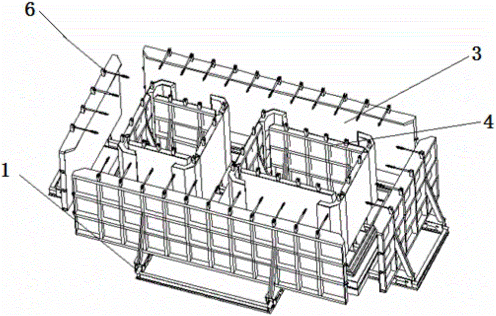
[0205] 1) Mold assembly: clean the mold, apply release agent, fix the mold base 1 on the ground, place the steel skeleton, install the socket end mold 2, install the inner mold mold 4, install the outer mold mold 3, and lock the locking device 6 ;

[0206] 2) Feeding and vibrating: concrete pouring and vibrating; concrete molding and plastering;

[0207] 3) Steam curing: steam curing is adopted, and a supporting canvas steam curing cover is used;

[0208] 4) Demoulding: Demoulding in the reverse order of mold assembly.

[0209] Preferably, the method also includes:

[0210] 5) Pipe gallery overturning: use hydraulic overturning equipment to turn the...

Embodiment 1

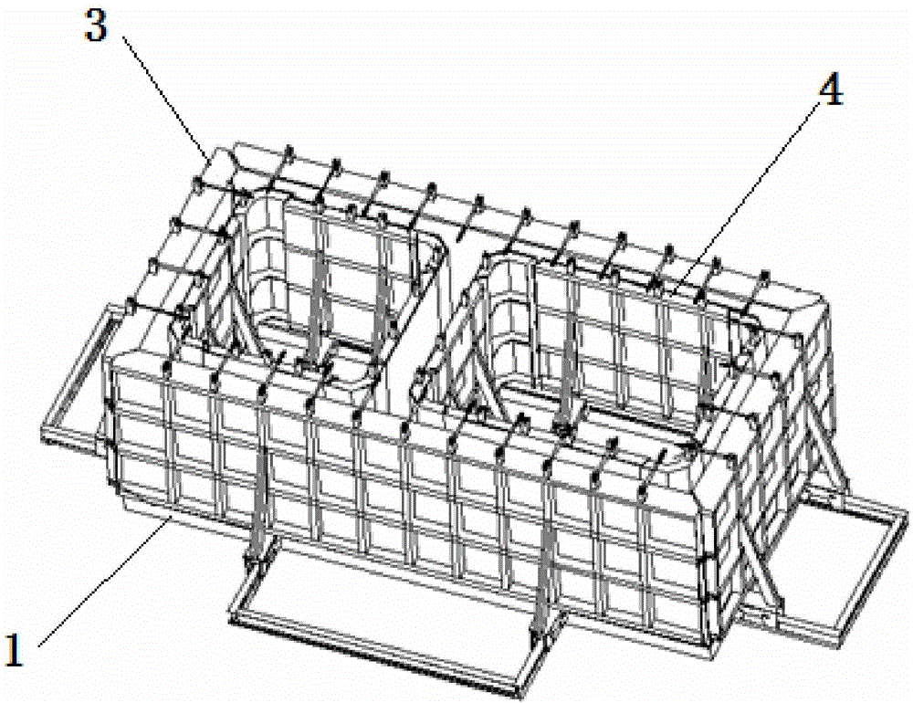
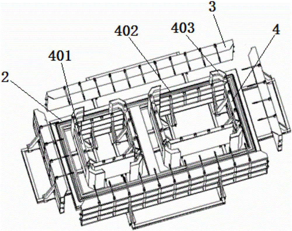
[0214] A vertical forming mold for a concrete comprehensive pipe gallery, the mold includes a mold base 1, a socket end mold 2, an outer mold mold 3, and an inner mold mold 4. Wherein: the mold base 1 is fixed on the ground. The socket end mold 2 is arranged on the mold base 1 . The outer mold 3 is arranged on the mold base 1 and is located around the outside of the socket-end mold 2 . Three internal molds 4 are arranged on the mold base 1 and are located around the inner side of the socket end mold 2 . The length of the entire inner mold is 8m; the height is 3.6m; the width is 2m. The 3 insider molds are the same size.

[0215] Outer mold guide rails 101 are respectively provided around the outside of the mold base 1 . The outer mold guide rails 101 on each side of the mold base 1 are perpendicular to the edges on each side of the mold base 1 . The outer mold guide rail 101 is an I-shaped steel guide rail. The inner side of the mold base 1 is provided with an inner mold...

Embodiment 2

[0220] Example 1 is repeated except that the mold comprises two inner mold molds 4 . Wherein the length of the entire inner mold mold is 6m. The width is 2m. The height is 3m.


PUM


Abstract

The invention discloses a vertical molding mold for a concrete utility tunnel. The vertical molding mold comprises a mold base (1), a female end mold (2), an external mold (3) and one or more internal molds (4). The mold base (1) is fixed on the ground, the female end mold (2) is arranged on the mold base (1), the external mold (3) is arranged on the mold base (1) and located on the periphery of the outer side of the female end mold (2), one or more internal molds (4) are arranged on the mold base (1) and located on the periphery of the inner side of the female end mold (2). The molding mold and system and production technology for the concrete single-cabin, dual-cabin and multiple-cabin utility tunnel is high in quality and large in scale and can be rapidly and largely produced.

Description

technical field [0001] The invention belongs to the technical field of moulds, and in particular relates to a vertical forming mould, system and application method of a concrete comprehensive pipe gallery. Background technique [0002] Urban underground "comprehensive pipe corridor" refers to the construction of an intensive tunnel in the underground space of urban roads, which integrates various municipal pipelines such as electricity, communications, water supply and drainage, heat, and gas, and implements "unified planning, unified construction, and unified construction". "Management" comprehensive pipe corridor is an effective way to rationally utilize underground space resources, solve the problems of insufficient capacity of various underground pipe network facilities, fragmentation, dissection, and repeated construction, and promote the comprehensive utilization of underground space and resource sharing. [0003] Most of the existing comprehensive pipe galleries adopt...

Claims


Application Information

Patent Timeline
IPC IPC(8): B28B7/18B28B7/24B28B7/00B28B11/24B28B1/087B28B1/08
CPCB28B7/18B28B1/081B28B1/087B28B7/0002B28B7/241B28B11/245
Inventor 江中凡
Owner CHANGSHA CHUHONG MACHINERY
Why Eureka
Try Eureka