Centralized arrangement mechanism of multiple air cylinders for vehicle
A technology for air storage tanks and vehicles, which is applied to the layout of reservoirs, vehicle components, elastic suspensions, etc., can solve the problems of increasing fixed points, rising production costs, high labor intensity, etc., to facilitate installation and disassembly, and reduce installation man-hours. , the effect of reducing labor intensity
- Summary
- Abstract
- Description
- Claims
- Application Information
AI Technical Summary
Problems solved by technology
Method used
Image

Examples
Embodiment 1
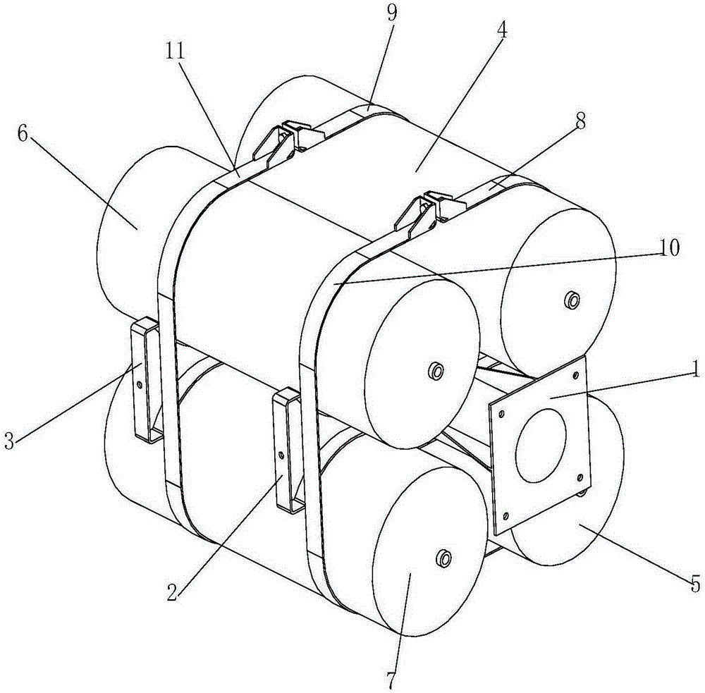
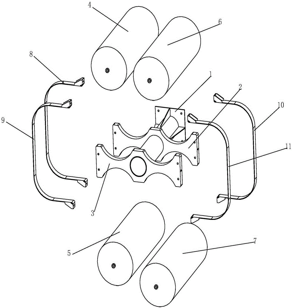
[0053] This embodiment provides a centralized arrangement mechanism for multiple air storage tanks for vehicles, such as figure 2 As shown, it includes a mounting beam assembly 1 , a first mounting bracket 2 , a second mounting bracket 3 , a first hoop 8 , a second hoop 9 , a third hoop 10 and a fourth hoop 11 .
[0054] like Figure 7 As shown, the above-mentioned mounting beam assembly 1 includes a connecting plate 1.1 and a mounting beam 1.2 arranged on the connecting plate 1.1, a reinforcing rib 1.3 is provided between the mounting beam 1.2 and the connecting plate 1.1, and the edge position of the connecting plate 1.1 There are mounting holes 1.4 for connecting with the vehicle frame.
[0055] like Figure 8 As shown, the above-mentioned first mounting bracket 2 includes a first web 2.1, a first through hole 2.2 is provided between the left and right ends of the first web 2.1, and the left top and bottom of the first web 2.2 are respectively provided with The first up...
Embodiment 2
[0061] This embodiment is basically the same as Embodiment 1, the difference between the two is:
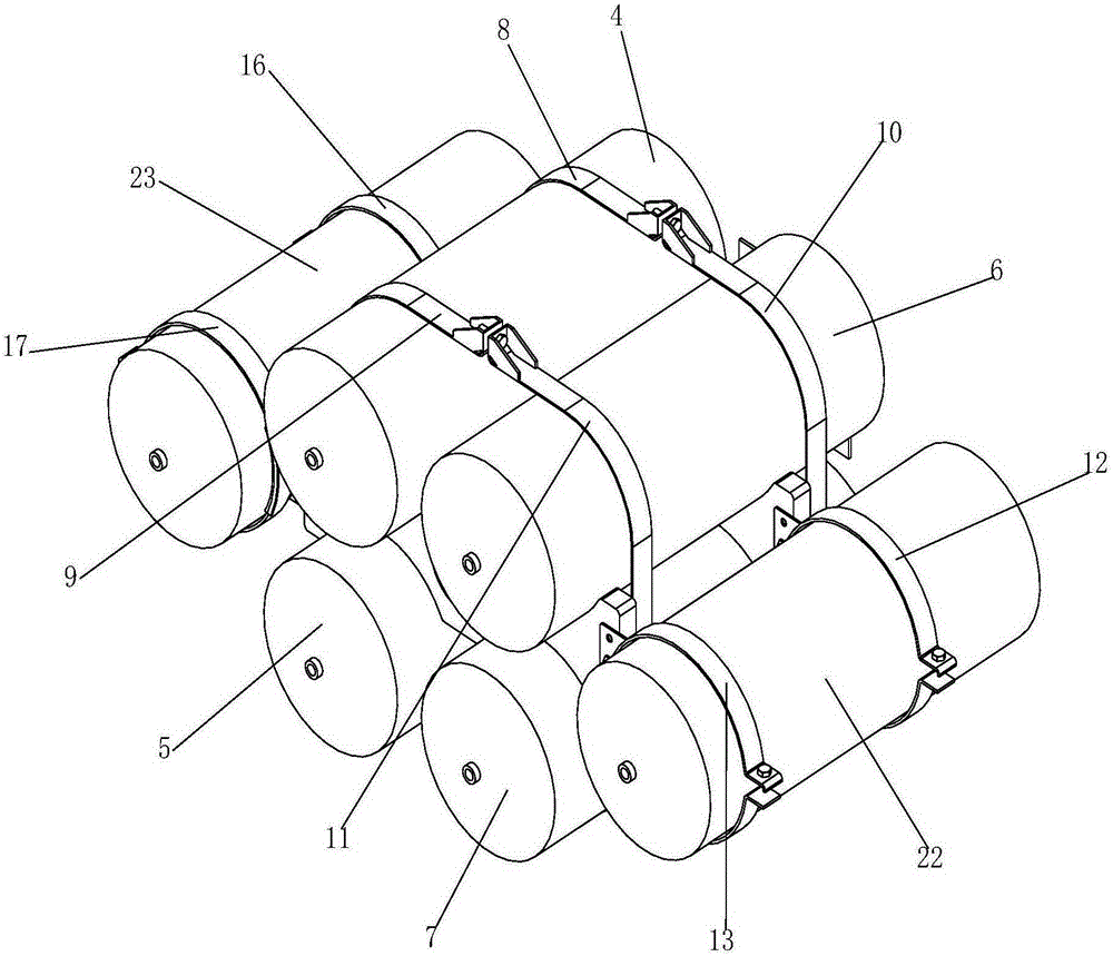
[0062] like Figure 4 As shown, the present embodiment also includes a fifth hoop 12, a sixth hoop 13, a seventh hoop 16, an eighth hoop 17, and a first mounting plate 14 and a second mounting plate with “L”-shaped sections. 15. The third mounting plate 18 and the fourth mounting plate 19.
[0063] like image 3 As shown, the horizontal plate and the vertical plate of the first mounting plate 14 are detachably connected with the right end of the first web 2.1 and the fifth hoop 12 respectively; the horizontal plate and the vertical plate of the second mounting plate 15 are respectively connected with the second web The right end of the plate 3.1 is detachably connected to the sixth hoop 13; the horizontal plate and the vertical plate of the third mounting plate 18 are detachably connected to the left end of the first web 2.1 and the seventh hoop 16; the fourth mounting plate 19...
Embodiment 3
[0066] This embodiment is basically the same as Embodiment 1, the difference between the two is:
[0067] like Image 6 As shown, this embodiment includes a fifth hoop 12, a sixth hoop 13, a sixth mounting plate 21, and a first mounting plate 14, a second mounting plate 15, and a fifth mounting plate 20 whose sections are all in an “L” shape. .
[0068] like Figure 5 As shown, the horizontal plate and the vertical plate of the first mounting plate 14 are detachably connected with the right end of the first web 2.1 and the fifth hoop 12 respectively; the horizontal plate and the vertical plate of the second mounting plate 15 are respectively connected with the second web The right end of the plate 3.1 is detachably connected to the sixth hoop 13; the front and rear ends of the horizontal plate of the fifth mounting plate 20 are respectively detachably connected to the first web 2.1 and the left end of the second web 3.1, and the vertical plate is connected to the sixth The ...
PUM
 Abstract
Description
Claims
Application Information
 - R&D
- Intellectual Property
- Life Sciences
- Materials
- Tech Scout
- Unparalleled Data Quality
- Higher Quality Content
- 60% Fewer Hallucinations
Browse by: Latest US Patents, China's latest patents, Technical Efficacy Thesaurus, Application Domain, Technology Topic, Popular Technical Reports.
© 2025 PatSnap. All rights reserved.Legal|Privacy policy|Modern Slavery Act Transparency Statement|Sitemap|About US| Contact US: help@patsnap.com