Electric multistage actuating cylinder retracting and releasing locking device

A locking device and actuating cylinder technology, applied in the chassis and other directions, can solve the problems of complex inner cavity shape, damage to the transmission mechanism, and locking failure, etc., and achieve the effects of simple processing, high reliability, and convenient disassembly and assembly

Active Publication Date: 2017-01-25
NANJING UNIV OF AERONAUTICS & ASTRONAUTICS
View PDF6 Cites 13 Cited by
  • Summary
  • Abstract
  • Description
  • Claims
  • Application Information

AI Technical Summary

Problems solved by technology

The locking of traditional electric actuators is achieved by locking the motor. When the actuator is extended to the end position, the motor is powered off, and the locking brake coaxially connected with the motor is energized, and the motor shaft is limited by the friction of the brake pads. The rotation of the reusable vehicle achieves the purpose of locking the actuator. This locking method is suitable for the case of a small load. Under the action of a huge impact load during the landing process of the reusable carrier, it will cause damage to the transmission mechanism, thus locking Locking failure, some electric cylinder locking methods are mechanically reliable locking, but the shape of the inner cavity of the main parts of the locking device is very complicated and difficult to process

Method used


Image

  • Electric multistage actuating cylinder retracting and releasing locking device
  • Electric multistage actuating cylinder retracting and releasing locking device
  • Electric multistage actuating cylinder retracting and releasing locking device

Examples


Embodiment Construction

[0017] The present invention will be further described below in conjunction with accompanying drawing.

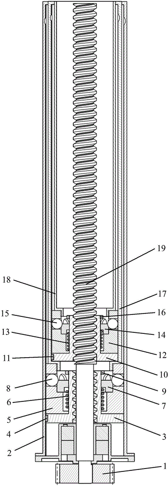
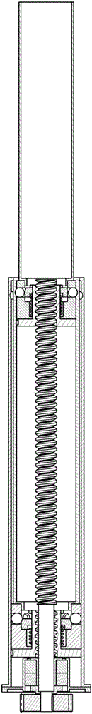
[0018] The invention provides an electric multi-stage actuator retractable locking device, the structure of which is as follows: figure 1 As shown, the expanded structure of the inner cylinder is as follows figure 2 As shown, the fully expanded structure is shown as image 3 As shown, it includes an outer cylinder 2, an intermediate cylinder 17, an inner cylinder 18, a lead screw 19 and a two-stage steel ball lock mechanism installed outside the lead screw 19. It is characterized in that: the two-stage steel ball lock mechanism includes a superior steel ball lock mechanism. Ball lock mechanism and lower steel ball lock mechanism.

[0019] The lower-level steel ball lock mechanism includes the lower sliding sleeve 5 (such as Figure 4 shown), the lower unlocking sleeve 3 (as shown Figure 5 shown), the lower locking slider 7 (as shown Figure 6 shown), the lower limit ...


PUM


Abstract

The invention provides an electric multistage actuating cylinder retracting and releasing locking device which comprises an outer cylinder, a middle cylinder, an inner cylinder, a screw and a two-stage steel ball lock mechanism mounted on the outer side of the screw. The outer cylinder, the middle cylinder and the inner cylinder are three coaxial sleeves which are sequentially embedded mutually, the middle cylinder and the inner cylinder are fixedly connected with the two-stage steel ball lock mechanism respectively, and the steel ball locking mechanism drives relative motion of upper and lower locking sliders and upper and lower sliding sleeve through joint action of the screw and upper and lower elastic elements so as to realize locking and unlocking of upper and lower steel balls; a steel ball lock is a mechanical lock, so that the device can bear high impact load in a locked state; an internal thread of the lower sliding sleeve does not be meshed with an external thread of the screw when a multistage actuating cylinder is at a fully-retracted position, and after the middle cylinder and the inner cylinder complete locking through an upper-stage steel ball lock mechanism, the inner cylinder drives the lower sliding sleeve to move upwards so as to be meshed with the screw to complete unfolding of the middle cylinder, so that due to this stage-by-stage unfolding mode, the multistage actuating cylinder is long in unfolding stroke and needless of manual operation in the process of retracting and releasing.

Description

technical field [0001] The invention relates to an electric multi-stage actuator retractable locking device, which is used for reusable landing legs of a carrier. Background technique [0002] With the successful launch and recovery of the reusable vehicle, the landing legs of the reusable vehicle are applied. As the retractable part of the landing outrigger, the traditional retractable form of the multi-stage actuator is pneumatic / hydraulic transmission. With the development and progress of technology, the electric actuator has been applied. Compared with the transmission electric actuator, the ratio of its length in the fully extended state to the length in the fully retracted state is usually small, which cannot meet the retractable size requirements of the landing legs of the reusable vehicle. Therefore, in order to realize The large expansion stroke of the actuator driven by the motor requires the design of a multi-stage continuous retractable mechanism. At the same t...

Claims


Application Information

Patent Timeline
Patent Type & Authority Applications(China)
IPC IPC(8): B64C25/26B64C25/24
CPCB64C25/24B64C25/26
Inventor 张明陶海峰岳帅肖杰夏昊天姜荣敏
Owner NANJING UNIV OF AERONAUTICS & ASTRONAUTICS
Why Eureka
Try Eureka