Motor-driven continuous circulating elevator system
An elevator system and motor-driven technology, applied in the mechanical field, can solve problems such as fading, limited transportation capacity, casualties, etc., and achieve the effect of large transportation volume
- Summary
- Abstract
- Description
- Claims
- Application Information
AI Technical Summary
Problems solved by technology
Method used
Image

Examples
Embodiment 1
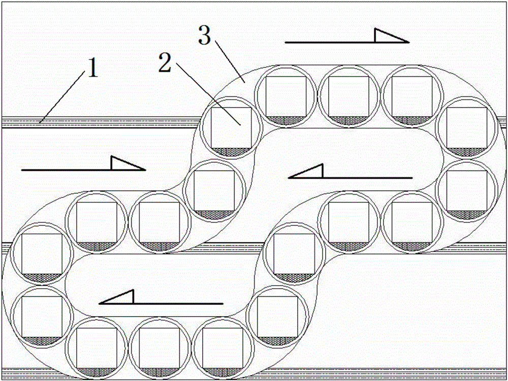
[0030] A motor-driven continuous circulation elevator system comprising a shaft 3 and a car 2,
[0031] Described shaft 3 comprises horizontal shaft 23, vertical shaft 21 and arc shaft 22, and horizontal shaft 23 is arranged on the floor of floor, and vertical shaft 21 is arranged between floors, and between horizontal shaft 23 and vertical shaft 21 Connected by arc shaft 22,
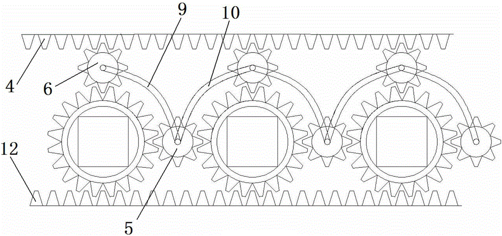
[0032] Two top surface rack tracks 4 are installed on the top surface of the horizontal shaft 23 and are continuously laid along the shaft including all the horizontal shafts 23, arc shafts 22 and vertical shafts 21 to form a closed circle; the two bottom rack tracks 12 Installed on the bottom surface of the horizontal shaft 23 and continuously laid along the shaft including all the horizontal shaft 23, the arc shaft 22 and the vertical shaft 21 to form a closed circle;
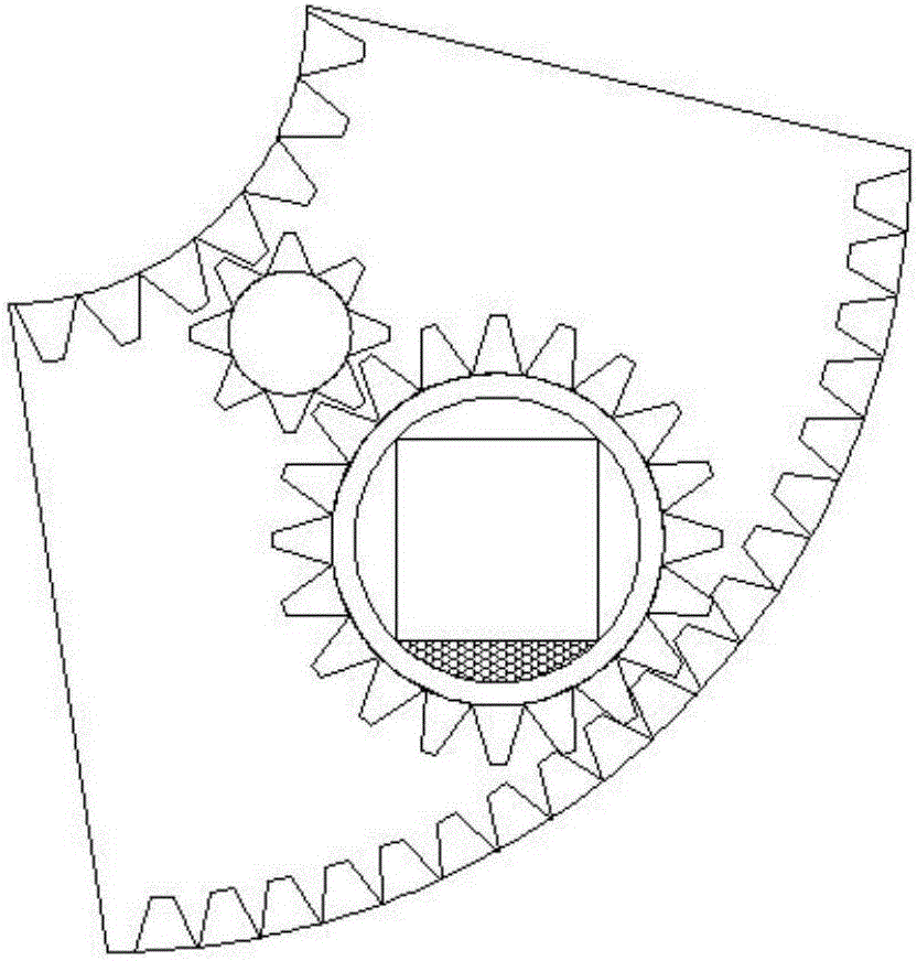
[0033] Described car 2 comprises cylinder liner 15, first travel bearing 14, second travel bearing 13, first transition gear 18, sec...
PUM
 Abstract
Description
Claims
Application Information
 - Generate Ideas
- Intellectual Property
- Life Sciences
- Materials
- Tech Scout
- Unparalleled Data Quality
- Higher Quality Content
- 60% Fewer Hallucinations
Browse by: Latest US Patents, China's latest patents, Technical Efficacy Thesaurus, Application Domain, Technology Topic, Popular Technical Reports.
© 2025 PatSnap. All rights reserved.Legal|Privacy policy|Modern Slavery Act Transparency Statement|Sitemap|About US| Contact US: help@patsnap.com