
Tower tube pouring construction method and tower tube

A construction method and tower tube technology, applied in the field of construction, can solve the problems of high construction costs, achieve low cost, ensure stability, and reduce the risk of internal mold instability

Inactive Publication Date: 2017-01-25
SANY ELECTRIC CO LTD
View PDF6 Cites 4 Cited by
  • Summary
  • Abstract
  • Description
  • Claims
  • Application Information

AI Technical Summary

Problems solved by technology

[0008] The purpose of the present invention is to provide a tower pouring construction method and tower, to solve the technical problem of high tower pouring construction cost in the prior art

Method used


Image

  • Tower tube pouring construction method and tower tube
  • Tower tube pouring construction method and tower tube
  • Tower tube pouring construction method and tower tube

Examples


Embodiment 1

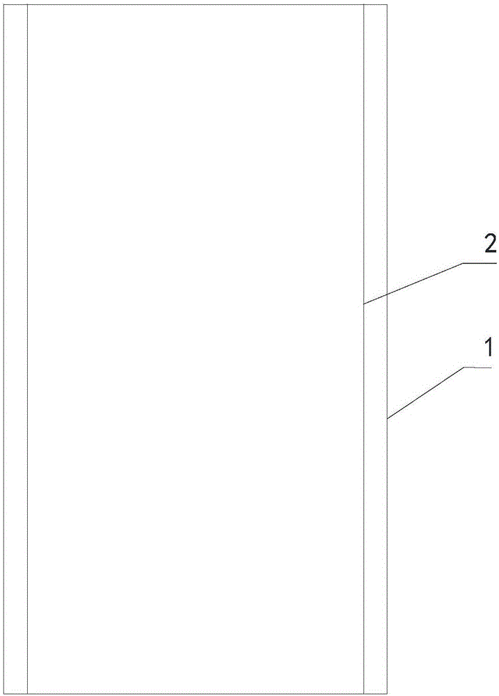
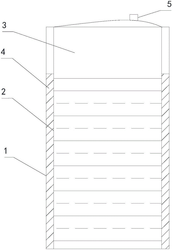
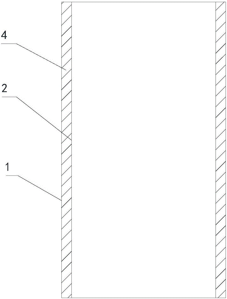
[0037] see figure 1 - image 3 as shown, figure 1 It is a schematic diagram of the structure of the outer mold and inner mold before the tower is poured, and no airtight cabin is placed; figure 2 It is a schematic diagram of the structure of the outer mold and the inner mold during the pouring process of the tower. In the figure, a sealed cabin has been placed inside the inner mold, and the tower is in a state of pouring a part. The fluid in the sealed cabin is basically the same height as the poured concrete; image 3 Schematic diagram of the outer formwork and inner formwork completed for the pouring of the tower, the airtight cabin has been removed. in figure 2 , image 3 The sloped hatch of is shown as a concreted tower.

[0038] see figure 1 - image 3 As shown, the tower pouring construction method provided in this embodiment includes:

[0039] Step 100, respectively setting an outer mold 1 and an inner mold 2 on both sides of the tower to be poured. It should...

Embodiment 2

[0067] In order to save space, the improved features of this embodiment are also reflected in figure 1 - image 3 in, therefore, combined with figure 1 - image 3 The configuration of this example will be described.

[0068] This embodiment provides a tower tube. This embodiment adopts the tower tube pouring construction method described in Embodiment 1, and the sealed cabin 3 that is arranged inside the inner mold 2 and can expand and contract makes it It can effectively reduce the risk of instability of the inner formwork 2, and has the advantages of convenient construction and low pouring construction cost.

[0069] Optionally, the tower 4 includes a poured concrete structure, and may also include an outer form 1 and / or an inner form 2 to improve the tensile performance of the tower 4 .


PUM


Abstract

The invention relates to the technical field of a building and particularly relates to a tower tube pouring construction method and a tower tube. The tower tube pouring construction method comprises the steps of: Step 100, respectively arranging an external mold and an internal mold on two sides of the tower tube to be poured; Step 200, arranging a sealed cabin capable of expansion and shrinkage in the internal mold; Step 300, pouring concrete between the external mold and the internal mold to form the tower tube; fluid is injected into the sealed cabin while concrete is poured, so that first acting force that the sealed cabin acts on the inner surface of the internal mold is no less than second acting force that concrete acts on the external surface of the internal mold. The tower tube is constructed by the tower tube pouring construction method. The invention aims at disclosing a tower tube pouring construction method and a tower tube, thereby solving a technical problem that the tower tube pouring construction cost is relatively high in a prior art.

Description

technical field [0001] The invention relates to the technical field of buildings, in particular to a construction method for pouring a tower tube and a tower tube. Background technique [0002] Wind energy is a new type of renewable energy with the most mature technology and the most large-scale development in the field of clean energy. In the past ten years, the global wind power field has advanced by leaps and bounds. From the previous 1.5MW wind turbines to the current popularization of 2MW wind turbines, from the 6MW and 8MW wind turbines put into operation, to the 10MW wind turbines have begun to be installed, and the wind turbine technology has advanced rapidly. [0003] The tower is the foundation of the entire wind turbine, and it mainly plays a supporting role in the wind turbine, and at the same time absorbs the vibration of the unit. At present, most of the domestic wind turbines are mainly made of traditional steel towers. [0004] With the increase of power ge...

Claims


Application Information

Patent Timeline
Patent Type & Authority Applications(China)
IPC IPC(8): F03D13/20E04G21/02
CPCE04G21/02Y02B10/30
Inventor 唐治平黄加佳潘勇
Owner SANY ELECTRIC CO LTD
Learn More