
Probe holding structure

A technology of probes and electrode substrates, which is applied to the parts, instruments, and measuring devices of electrical measuring instruments, which can solve the problems of increased maintenance costs and complicated replacement operations, and achieve the effect of improving position accuracy and reducing the minimum spacing

Active Publication Date: 2020-09-08
ORGAN NEEDLE CO LTD
View PDF10 Cites 0 Cited by
  • Summary
  • Abstract
  • Description
  • Claims
  • Application Information

AI Technical Summary

Problems solved by technology

[0006] However, if a thin linear probe is used, the maintenance cost increases and the replacement operation becomes complicated.

Method used


Image

  • Probe holding structure
  • Probe holding structure
  • Probe holding structure

Examples


Embodiment Construction

[0031] Embodiments of the present invention will be described with reference to the drawings.

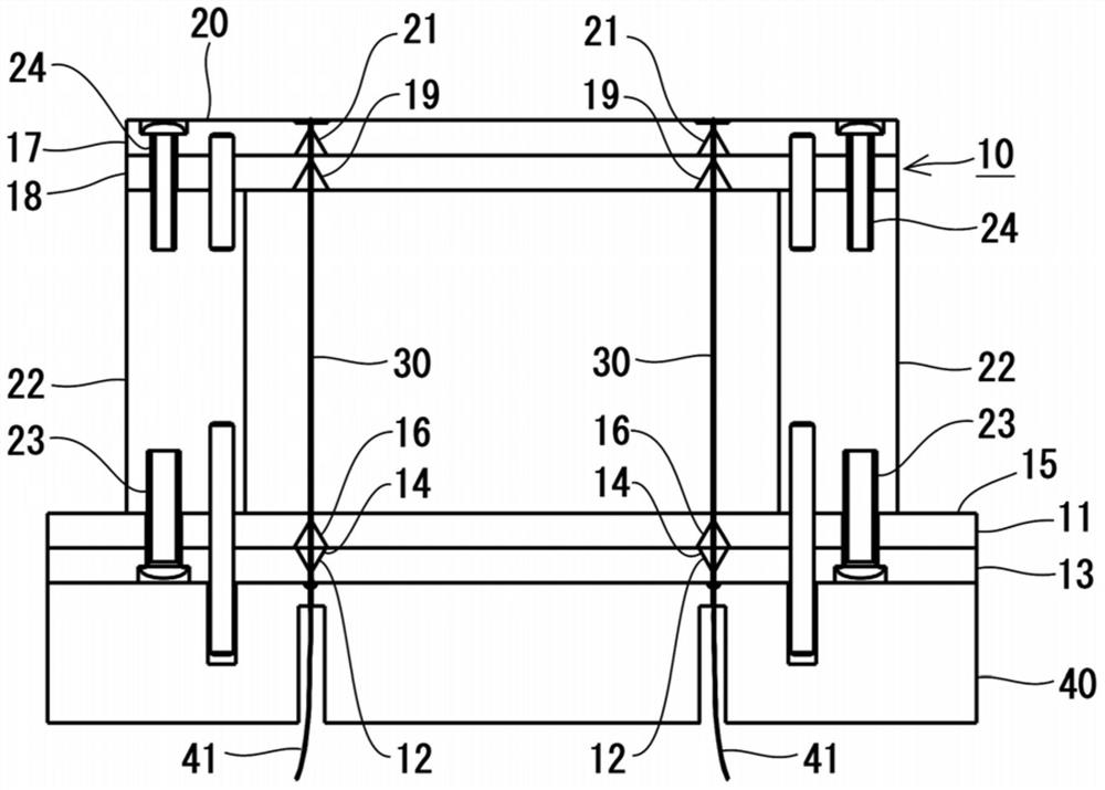
[0032] The holding structure of the probe 30 in this embodiment includes the probe 30 and the probe jig 10 that holds both ends of the probe 30 and is arranged between the electrode substrate 40 and the substrate to be inspected (not shown).

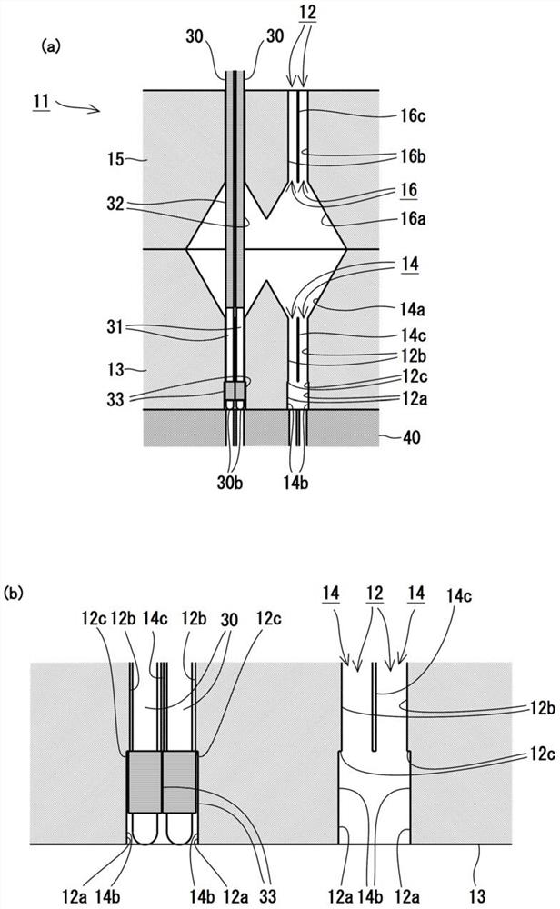
[0033] Such as figure 2 , etc., the probe 30 is a member having an insulating coating 32 and a locking portion 33 on the outer peripheral portion of a conductive metal pin 31 . The insulating coating 32 is an insulating coating covering the outer periphery of the metal pin 31 at the middle portion of the probe 30 . By providing the insulating coating 32 , even when the probe 30 is bent, insulation from other probes 30 is ensured. In addition, the locking portion 33 is an annular insulator attached to the outer periphery of the metal pin 31 in the vicinity of the rear end portion 30 b of the probe 30 . The locking portion 33 ensures the ins...


PUM


Abstract

The present invention provides a probe that can reduce the minimum pitch of the probes compared to conventional ones without making the tip of the probes into a special shape, and can reduce the minimum pitch of the probes without limiting the number of probes. Needle retention structure. The probe jig (10) includes a base (11) holding a rear end (30b) of a probe (30). The through hole (12) of the base (11) includes a large diameter portion (12a) facing the electrode substrate (40) and a small diameter portion (12b) continuous with the large diameter portion (12a). A stepped portion (12c) is formed between the large diameter portion (12a) and the small diameter portion (12b). The probe (30) includes an annular locking portion (33) built in the large-diameter portion (12a) and formed to have a larger diameter than the small-diameter portion (12b).

Description

technical field [0001] The present invention relates to a holding structure of a probe used in substrate inspection. Background technique [0002] Conventionally, in the conduction inspection and electrical characteristic inspection of semiconductor integrated circuits and the like (substrates to be inspected), inspections using extremely thin probes have been performed. For example, a method is known in which both ends of a plurality of probes are held by a probe jig, the probe jig is sandwiched between an electrode substrate and a substrate to be inspected, and the two ends of the probes are respectively connected to the terminals of the electrode substrate. The inspection is carried out by contacting the terminals of the substrate to be inspected. In such an inspection, when the electrodes of the object to be inspected are small, it is necessary to reduce the minimum pitch (arrangement interval) of the probes. [0003] However, in conventional probes, the minimum pitch ...

Claims


Application Information

Patent Timeline
Patent Type & Authority Patents(China)
IPC IPC(8): G01R1/073G01R1/04
CPCG01R1/0425G01R1/07371G01R1/06733G01R1/06744G01R1/07307G01R31/2886
Inventor 加藤靖典大西正树
Owner ORGAN NEEDLE CO LTD
Learn More