Coupling detector

A coupled detection and coupler technology, applied in the field of coupled detection, can solve the problems of affecting measurement accuracy, weak signal, and inability to obtain accuracy, and achieve the effect of improving measurement accuracy and reducing insertion loss

Pending Publication Date: 2017-01-25
CHNEGDU CHIFFO ELECTRONICS INSTR
View PDF14 Cites 4 Cited by
  • Summary
  • Abstract
  • Description
  • Claims
  • Application Information

AI Technical Summary

Problems solved by technology

[0003] As a key part of the RF power reflectometer, the coupler affects the measurement accuracy to a great extent. When the dynamic range of the measured power is large, and in order to ensure extremely small insertion loss, it is coupled to the detector diode during low power measurement The signal is very weak, and the existing coupled detectors cannot obtain high-precision measurement results

Method used


Image

  • Coupling detector
  • Coupling detector

Examples


Embodiment 1

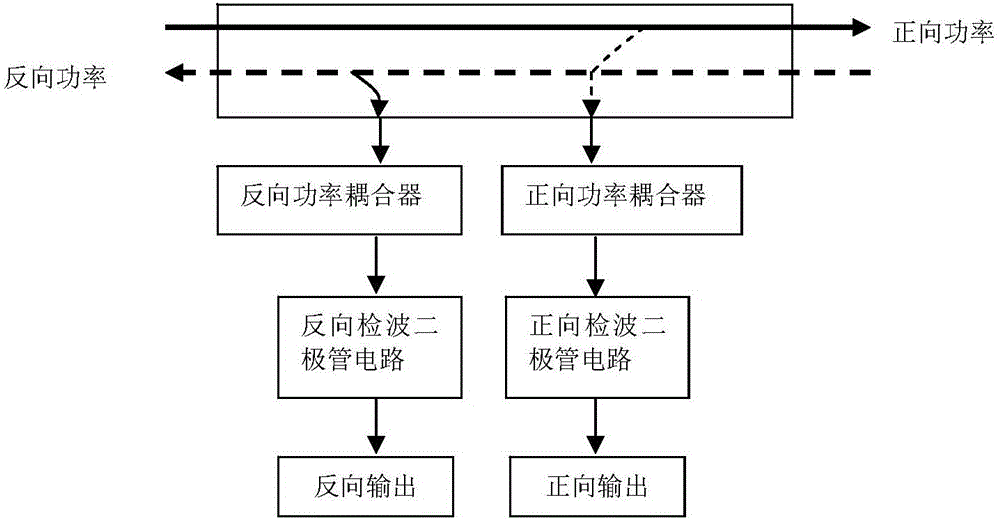
[0018] figure 1 Shown is the modular block diagram of the coupling detector of the present invention, comprises reverse power coupler, forward power coupler, reverse detection diode circuit, forward detection diode circuit;

[0019] Both the reverse power coupler and the forward power coupler are connected to the load under test for measuring forward power data and reverse power data of the load under test;

[0020] The reverse power coupler is connected to the reverse detection diode, and the forward power coupler is connected to the forward detection diode for performing detection processing on the forward power data and reverse power data, and The processed data is output.

[0021] In a specific implementation manner, both the reverse power coupler and the forward power coupler are directional couplers.

[0022] In a specific embodiment, the directional coupler is a coaxial coupling.

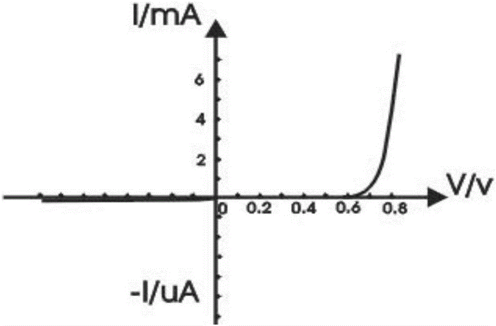
[0023] In a specific implementation manner, both the reverse detection diode and the f...


PUM


Abstract

The invention discloses a coupling detector which comprises a back power coupler, a forward power coupler, a back detection diode circuit and a forward detection diode circuit, wherein the back power coupler and the forward power coupler are connected with a detected load, and are used for measuring forward power data and back power data of the detected load; and the back power coupler is connected with a back detection diode, and the forward power coupler is connected with a forward detection diode, so that the forward power coupler and the back power coupler are used for detecting the forward power data and the back power data and outputting the processed data. By the adoption of a double-coupling technology and connection of each coupling port with the corresponding detection diode circuit, when the dynamic range of measured power is large, extremely low insertion loss can be guaranteed; and meanwhile, a very weak signal coupled to each detection diode is precisely measured during low-power measurement, so that the measurement precision is improved.

Description

technical field [0001] The invention relates to the field of coupling detection, in particular to a coupling detection device. Background technique [0002] Power reflectometers are commonly used to measure the power of radio frequency (RF) or microwave frequency (MW) signals. A typical power reflectometer uses a power detector or transducer to convert RF or MW power into an easily measurable electrical quantity. Power reflectometers also have applications in many types of RF and MW systems. [0003] As a key component in the RF power reflectometer, the coupler affects the measurement accuracy to a great extent. When the dynamic range of the measured power is large, and in order to ensure extremely small insertion loss, it is coupled to the detector diode during low power measurement The signal is very weak, and the existing coupled detectors cannot obtain high-precision measurement results. Contents of the invention [0004] The present invention overcomes the above-me...

Claims


Application Information

Patent Timeline
Patent Type & Authority Applications(China)
IPC IPC(8): G01R21/10
CPCG01R21/10
Inventor 李杰杨如福
Owner CHNEGDU CHIFFO ELECTRONICS INSTR
Why Eureka
Try Eureka