Transient-state quantity polarity comparison type bus protection method on basis of sequence overlapping and differential transformation
A technology of overlapping differential and busbar protection, applied in the direction of measuring electrical variables, measuring electricity, measuring devices, etc., can solve problems such as poor anti-CT saturation capability, and achieve the effect of high reliability, good effect, and accurate judgment.
- Summary
- Abstract
- Description
- Claims
- Application Information
AI Technical Summary
Problems solved by technology
Method used
Image
Examples
Embodiment 1
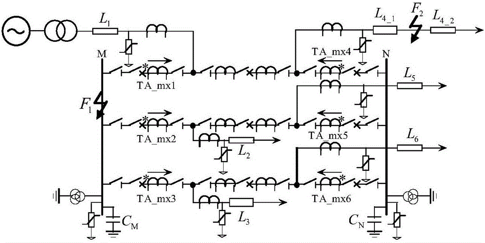
[0052] Example 1: Take figure 1 In the simulation model, a metallic single-phase ground fault occurs on the bus M, the sampling frequency is 500kHz, F1 and F2 are A-phase metallic ground faults, and the initial fault angle is 90°. The bus-side current transformers CT1, CT2, CT3 constitute the bus-bar M side protection. The three-phase current and the three-phase voltage are respectively subjected to phase-to-mode conversion to obtain the line-mode current and line-mode voltage of the faulty phase.
[0053] The specific steps of the method are:
[0054] 1. When the bus or line fails, the measuring unit will take the bus voltage data from 1ms before the failure to 2ms after the failure and the current data of each line;
[0055] 2. Perform sequence overlap and differential transformation on the fault signal; transform the line mode voltage and line mode current according to the sequence overlap difference method, and the conversion results are Su(n) and Si(n);
[0056] 3. Calculate SP...
Embodiment 2
[0059] Example 2: Take figure 1 In the simulation model, a metallic single-phase grounding fault occurs at bus M, and the sampling frequency is 500kHz. A metallic single-phase grounding fault occurs at line L1 at a distance of 70km from bus M. The initial angle of the fault is 90° bus-side current transformer CT1 CT2 and CT3 constitute the M side protection of the bus. The three-phase current and the three-phase voltage are respectively subjected to phase-to-mode conversion to obtain the line-mode current and line-mode voltage of the faulty phase.
[0060] The calculated current measured at each measuring point on the bus M and the calculated result are as follows image 3 Shown.
[0061] From the simulation results, it can be seen that the current sudden change direction of the faulty line is opposite to the current sudden change direction of the healthy line. The calculation result is 1, which is judged as a line fault, which is consistent with the assumption, and the judgment ...
PUM
 Abstract
Description
Claims
Application Information
 - R&D
- Intellectual Property
- Life Sciences
- Materials
- Tech Scout
- Unparalleled Data Quality
- Higher Quality Content
- 60% Fewer Hallucinations
Browse by: Latest US Patents, China's latest patents, Technical Efficacy Thesaurus, Application Domain, Technology Topic, Popular Technical Reports.
© 2025 PatSnap. All rights reserved.Legal|Privacy policy|Modern Slavery Act Transparency Statement|Sitemap|About US| Contact US: help@patsnap.com


