Magnetic shielding of x-ray emitters

An x-ray and transmitter technology, applied in the field of x-ray transmitters, can solve problems such as resolution degradation of x-ray systems, and achieve the effects of improving processing and diagnosis efficiency, reducing interference, and improving image resolution

Inactive Publication Date: 2018-07-03
SIEMENS HEALTHCARE GMBH
View PDF5 Cites 0 Cited by
  • Summary
  • Abstract
  • Description
  • Claims
  • Application Information

AI Technical Summary

Problems solved by technology

The movement of the focal point degrades the resolution of the x-ray system

Method used


Image

  • Magnetic shielding of x-ray emitters
  • Magnetic shielding of x-ray emitters
  • Magnetic shielding of x-ray emitters

Examples


Embodiment Construction

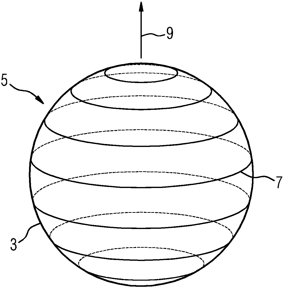
[0063] figure 1 An exemplary embodiment of a schematic diagram of a spherical housing 3 of an x-ray tube 5 is shown. The x-ray tube 5 includes an anode (eg a rotating anode or a stationary anode) and a cathode (not shown). Additional components (such as anode drivers, leads and terminals) may be present. Also, protrusions and / or indentations may be present on the spherical surface for feeding and / or receiving other components. Electrons emitted by the cathode are accelerated towards the anode along the electron flow trajectory. The electron flow trajectory is aligned parallel to the direction of the electron flow trajectory 9 specified in the figure. The ferromagnetic particles are aligned along a closed path 7 extending approximately in a plane perpendicular to the direction of the electron flow trajectory 9 . A path 7 arranged according to the parallels on the spherical surface occurs for the spherical shell 3 . The ferromagnetic particles generally do not form an end-t...


PUM


Abstract

A magnetic shield for an x-ray emitter is provided. The present invention relates to an x-ray emitter having a housing, wherein the housing has a diamagnetic or paramagnetic housing material and also has a plurality of ferromagnetic particles, and wherein the ferromagnetic particles are generally aligned along a closed path. The invention also relates to a medical device with an inventive x-ray emitter and a method for producing an inventive x-ray emitter.

Description

technical field [0001] The present invention relates to x-ray emitters and methods for producing x-ray emitters. Background technique [0002] An x-ray emitter consists of an x-ray tube and a housing surrounding the x-ray tube. The x-ray tube itself also includes an envelope, usually embodied as a vacuum envelope. Both types of enclosures typically include soft magnetic materials. [0003] X-ray emitters and particularly x-ray tubes are used in a variety of medical devices including, for example, radiography systems, angiography systems with one or several C-arms, and computed tomography systems. [0004] Publication DE 19901482 B4 specifies a multi-examination apparatus with multiple imaging systems arranged in a room so that a patient lying on a movable patient support bed can be in the imaging system without changing position Examinations are carried out in any of the above wherein, in addition to a magnetic resonance system with actively shielded magnets, a soft magne...

Claims


Application Information

Patent Timeline
Patent Type & Authority Patents(China)
IPC IPC(8): H01J35/16H01J35/14H01J9/24
CPCH01J35/16A61B6/40A61B6/461H01J9/00H01J2235/166H05G1/04
Inventor R·卡斯N·皮科特
Owner SIEMENS HEALTHCARE GMBH
Why Eureka
Try Eureka