
Semiconductor device and manufacture method

A manufacturing method and semiconductor technology, applied in semiconductor/solid-state device manufacturing, semiconductor devices, semiconductor/solid-state device components, etc., can solve the problems of difficulty in meeting the heat dissipation requirements of high-power chips and low heat transfer effect

Inactive Publication Date: 2017-01-25
HUAWEI TECH CO LTD
View PDF4 Cites 4 Cited by
  • Summary
  • Abstract
  • Description
  • Claims
  • Application Information

AI Technical Summary

Problems solved by technology

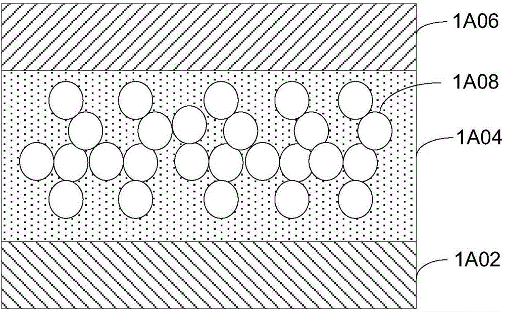
Among them, the thermal interface material layer 1A04 has a plurality of metal particles 1A08 distributed in the form of a dispersed phase, and the heat generated by the integrated circuit chip 1A02 during operation is poured into the heat sink 1A06 through the thermal interface material layer 1A04 on the back of the chip, but the existing In technology, due to the limited size of the circuit chip 1A02, the heat transfer effect is low, and it is difficult to meet the heat dissipation requirements of high-power chips.

Method used


Image

  • Semiconductor device and manufacture method
  • Semiconductor device and manufacture method
  • Semiconductor device and manufacture method

Examples


Embodiment Construction

[0046] The following will clearly and completely describe the technical solutions in the embodiments of the present invention with reference to the accompanying drawings in the embodiments of the present invention. Obviously, the described embodiments are only some, not all, embodiments of the present invention. Based on the embodiments of the present invention, all other embodiments obtained by persons of ordinary skill in the art without creative efforts fall within the protection scope of the present invention.

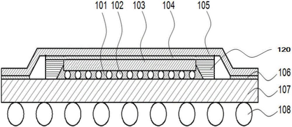
[0047] For the convenience of description, this embodiment defines the side wall of the circuit device. In this embodiment, the side wall of the circuit device refers to the wall adjacent to the side (mounting surface) on the circuit device that is provided with pins. Figure 1B middle, Figure 1B The cross-sectional illustration of the semiconductor device provided in the first embodiment of the present invention, with the placement direction of the semiconductor ...


PUM


Abstract

The invention relates to the field of circuits and discloses a semiconductor device and a manufacture method. The semiconductor device comprises a circuit device, a cooling fin and a thermal interface material layer located between the circuit device and the cooling fin, wherein the circuit device and the cooling fin are arranged in a laminating manner; a packaging layer surrounds the side wall of the circuit device; a first surface of the thermal interface material layer is in thermal coupling with the circuit device and the packaging layer, and a second surface is in thermal coupling with the cooling fin. In the scheme, the packaging layer and the circuit device are both in thermal coupling with the thermal interface material layer, so that the contact area of the circuit device with the thermal interface material layer is increased, heat produced on the side wall of the circuit device can be transferred to the thermal interface material layer through the packaging layer and then transferred to the cooling fin, and the cooling effect of the semiconductor device is improved. By means of the packaging layer surrounding the circuit device, the laying area of the thermal interface material layer is increased, the area of a contact surface of the thermal interface material layer is increased, the interfacial stress is reduced, and the component reliability is improved correspondingly.

Description

technical field [0001] The invention relates to the technical field of semiconductors, in particular to a circuit semiconductor device and a manufacturing method. Background technique [0002] Figure 1A Shown is an exemplary cross-sectional view of an integrated circuit chip and a part of its packaging structure in the prior art. The structure includes an integrated circuit chip 1A02 , a thermal interface material layer 1A04 and a heat sink 1A06 . Among them, the thermal interface material layer 1A04 has a plurality of metal particles 1A08 distributed in the form of a dispersed phase, and the heat generated by the integrated circuit chip 1A02 during operation is poured into the radiator 1A06 through the thermal interface material layer 1A04 on the back of the chip, but the existing In technology, due to the limitation of the size of the circuit chip 1A02 , the effect of heat transfer is low, and it is difficult to meet the heat dissipation requirements of high-power chips....

Claims


Application Information

Patent Timeline
IPC IPC(8): H01L23/31H01L23/373H01L21/48H01L21/56B82Y30/00
CPCB82Y30/00H01L21/4882H01L21/56H01L23/3185H01L23/3736H01L2224/16227H01L2224/32225H01L2224/73204H01L2224/73253H01L2924/15311H01L2924/16251H01L23/3128H01L23/42H01L2224/16225H01L2924/00H01L23/31H01L23/367H01L23/3733H01L23/3735H01L23/49816H01L24/16H01L24/29H01L24/32H01L2224/29082H01L2224/29083H01L2224/29124H01L2224/29139H01L2224/29144H01L2224/29147H01L2224/29155H01L2224/29166H01L2224/29171H01L2224/29172H01L2224/32221
Inventor 林志荣黄文浚
Owner HUAWEI TECH CO LTD
Learn More