Feed source locating and focus offset device for compact range measurement

A technology of compact field and feed source, which is applied in the direction of antenna grounding switch structure connection, electrical components, waveguide horn, etc., can solve the problems of single function, complicated adjustment process, difficult error, etc., and achieve increased accuracy, convenient operation, and high speed. fast effect

Active Publication Date: 2017-01-25
BEIHANG UNIV
View PDF2 Cites 30 Cited by
  • Summary
  • Abstract
  • Description
  • Claims
  • Application Information

AI Technical Summary

Problems solved by technology

The adjustment process is more complicated and less efficient
During the test, the polarization rotation of the feed needs to be manually switched. According to the position of the positioning hole, the angle of polarization rotation is several fixed values, which greatly limits the scope of the test.
In the process of debugging, switching, etc., the position of the positioning hole is used for positioning, so the positioning accuracy is guaranteed by the machining accuracy of the positioning part, and the resulting error is difficult to correct.
In addition, the fixed bracket cannot realize the off-focus movement of the feed source, making the function become single during the tight field test

Method used


Image

  • Feed source locating and focus offset device for compact range measurement
  • Feed source locating and focus offset device for compact range measurement
  • Feed source locating and focus offset device for compact range measurement

Examples


Embodiment 1

[0039] Embodiment one: on-site installation and adjustment.

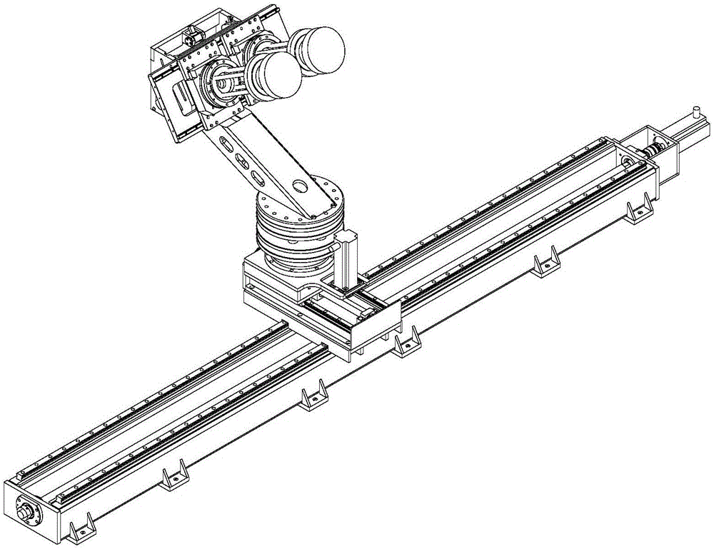
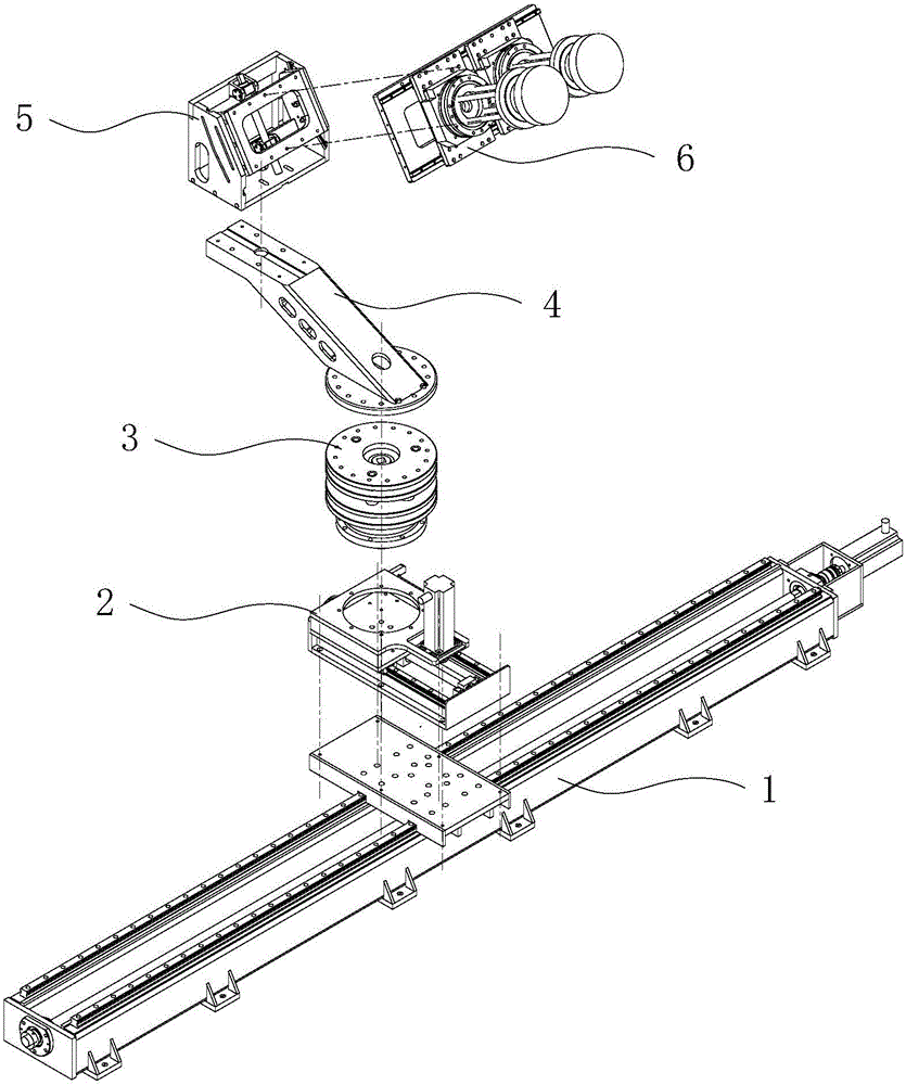
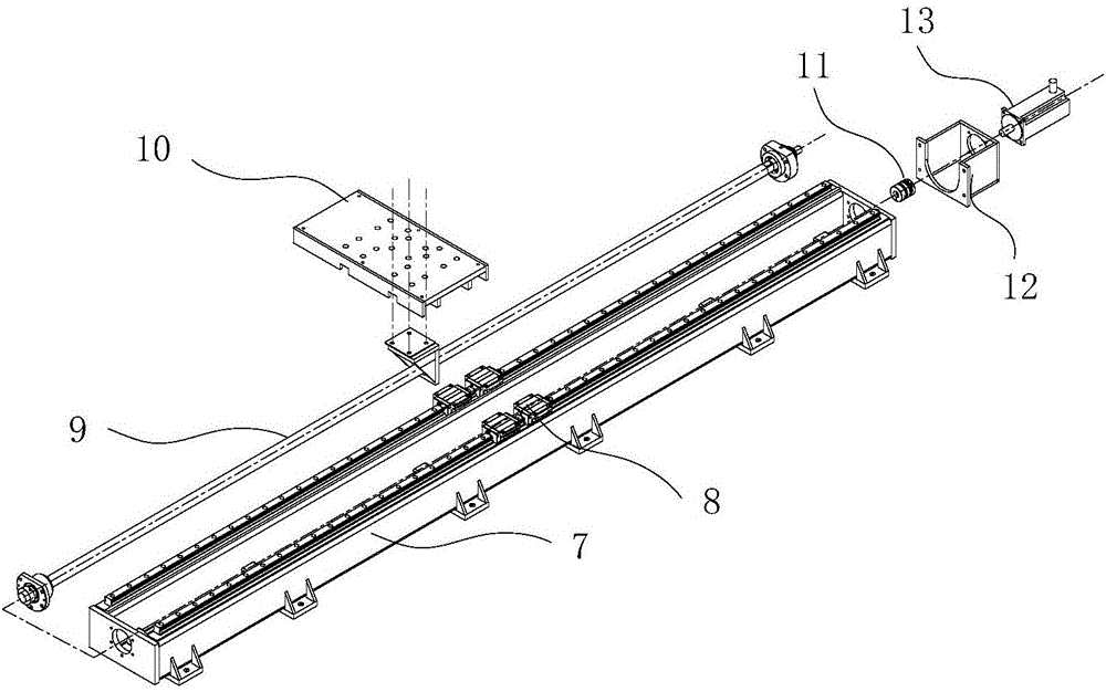
[0040] The phase center of the feed source will eventually be positioned at the focal point of the reflective surface, and the positioning deviation is required to be better than one-tenth of the wavelength (the wavelength of the maximum operating frequency of the compact field). During the on-site installation process, the X-direction base 7 is installed on the anchor bolts on the site, and the rough height adjustment of the feed source positioning device is mainly completed during installation. It is measured by using a laser tracker, and by adjusting the height of the nuts on the anchor bolts, Adjust the installation of the X-direction mobile unit 1 to a horizontal state. In order to ensure that the direction of the entire guide rail (X direction) is perpendicular to the direction of the electric axis of the compaction field (Y direction), it is necessary to use a laser tracker to adjust the linear guide rail in t...

Embodiment 2

[0041] Embodiment 2: Measuring the antenna in a non-defocused state.

[0042] Figures 10a, 10b, 10c and 10d are the isometric view, top view, front view and right view of the feed source positioning and the position and posture of the defocus device when measuring the antenna in the non-defocus state, respectively. In this test state, only one feed horn is needed. The horn is located on the electrical axis of the compact field, and its phase center is located on the axis of the electrical axis, which coincides with the focus of the reflective surface and faces the reflective panel. The beam deflection angle is 0° . The spherical wave emitted by the feed becomes a plane wave after passing through the reflector. During the antenna measurement process, the feed horn has two measurement states: measurement at a certain polarization angle and measurement at a constant speed. This test state can measure data such as the pattern of the antenna.

Embodiment 3

[0043] Embodiment 3: Measuring the antenna in a defocused state.

[0044] Figures 11a, 11b, 11c, and 11d are the isometric view, top view, front view and right view of the feed source positioning and the position and posture of the defocus device when measuring the antenna in the defocus state, respectively. In this test state, only one feed horn is needed. The position of the horn deviates from the electric axis of the compact field, its phase center is located on a specific defocus trajectory, and the beam deflection angle ranges from -9° to 9°. On the defocused trajectory, the spherical wave emitted by the feed source becomes an approximate plane wave with the best effect after passing through the reflecting surface. During the antenna measurement process, the feed horn has two measurement states: measurement at a certain polarization angle and measurement at a constant speed. This experiment can measure data such as the pattern of the antenna.


PUM


Abstract

The invention provides a feed source locating and focus offset device for compact range measurement. The device is used for precise location and focus offset motion of a feed horn in an electromagnetic measurement process of a compact range. The device mainly comprises left and right transverse movement along the X axis, front and back longitudinal movement along the Y axis, rotation and translation around the Z axis and pitching movement around the phase center of a feed source. Accurate locating and focus offset of the feed source are realized through movement of five freedom degrees, and focus offset measurement is completed. By means of servo control, polarization rotation and uniform rotation at a certain rotation speed of the feed horn can be realized, and RCS (radar cross-section) measurement or antenna measurement is completed. The device comprises an X-axial moving unit, a Y-axial compensation unit, a Z-axial rotating and height adjusting unit, an offset arm, a feed source pitching unit and a feed source polarization unit. Different from a fixed feed source locating device, the device can not only be used for precise location of the feed source during measurement of the compact range in a traditional manner, but also be used for measurement of new demand ways such as focus offset and the like; the device has the advantages of high measurement efficiency, high locating precision and simple and reliable control process.

Description

technical field [0001] The invention relates to a feed source positioning and defocusing device for compact field measurement, which is suitable for precise positioning and defocusing movement of a feed source horn in the process of compact field electromagnetic measurement, and belongs to the fields of mechanical engineering and microwave engineering. Background technique [0002] The feed positioning device is an important part of the compact field measurement system. The feed source horn is connected with the positioning device through the extension frame to form a whole. The feed positioning device can realize the precise adjustment of 6 degrees of freedom of the feed phase center, and realize the precise positioning of the feed. The positioning accuracy of the positioning device directly affects the positioning accuracy of the phase center of the feed horn. During the measurement, the equivalent phase center of the feed must be strictly located on the focus of the par...

Claims


Application Information

Patent Timeline
Patent Type & Authority Applications(China)
IPC IPC(8): H01Q13/02H01Q1/50H01Q3/08
CPCH01Q1/50H01Q3/08H01Q13/02
Inventor 李东升王明明罗红宇金垚贤
Owner BEIHANG UNIV
Why Eureka
Try Eureka