
An agricultural centrifugal fertilizer application device

A centrifugal and chemical fertilizer technology, applied in fertilization devices, fertilizer spreaders with centrifugal wheels, agriculture, etc., can solve the problems of uneven fertilizer spreading, inability to change the spreading range, low spreading efficiency, etc.

Active Publication Date: 2018-10-19
黑龙江省樱田农机制造有限公司
View PDF9 Cites 1 Cited by
  • Summary
  • Abstract
  • Description
  • Claims
  • Application Information

AI Technical Summary

Problems solved by technology

[0002] A few days ago, farmers need to spread chemical fertilizers in the fields during the busy season of farming. The traditional way of spreading chemical fertilizers is to hold the chemical fertilizers in a pot, and then grab the chemical fertilizers and spread them by hand. The second is that due to the corrosion of chemical fertilizers, it will hurt hands. In recent years, some fertilizer throwing devices have emerged, but most of them use storage barrels to discharge the material. The fertilizer falls on the rotating disk driven by the wheels, and the fertilizer is thrown out. , but these devices are mainly for throwing some granular fertilizers, and are not suitable for some fine-grained or flour-like fertilizers, and these devices need to manually crush large pieces of chemical fertilizers to avoid blocking the feeding port. The throwing range of these devices is fixed and cannot be changed. Therefore, in view of the above problems, there is an urgent need for a device that can automatically break up bulk fertilizers, adjust the throwing range, and be applicable to both granular and flour-like fertilizers. A device for spreading fertilizer

Method used


Image

  • An agricultural centrifugal fertilizer application device
  • An agricultural centrifugal fertilizer application device
  • An agricultural centrifugal fertilizer application device

Examples


Embodiment Construction

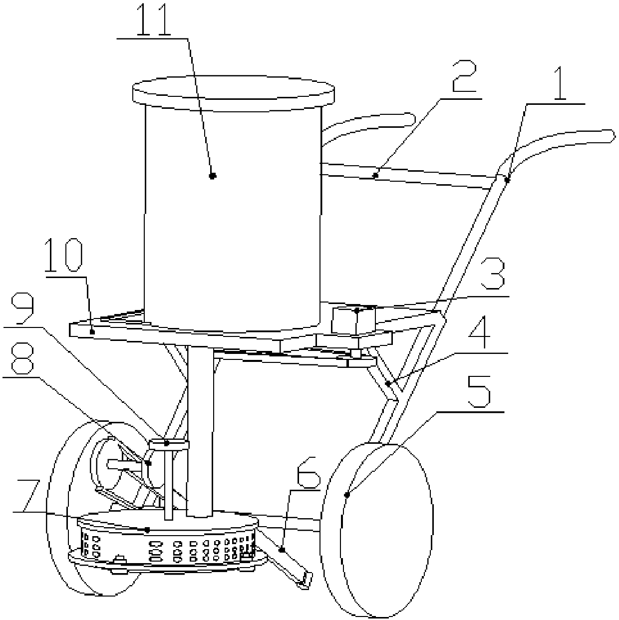
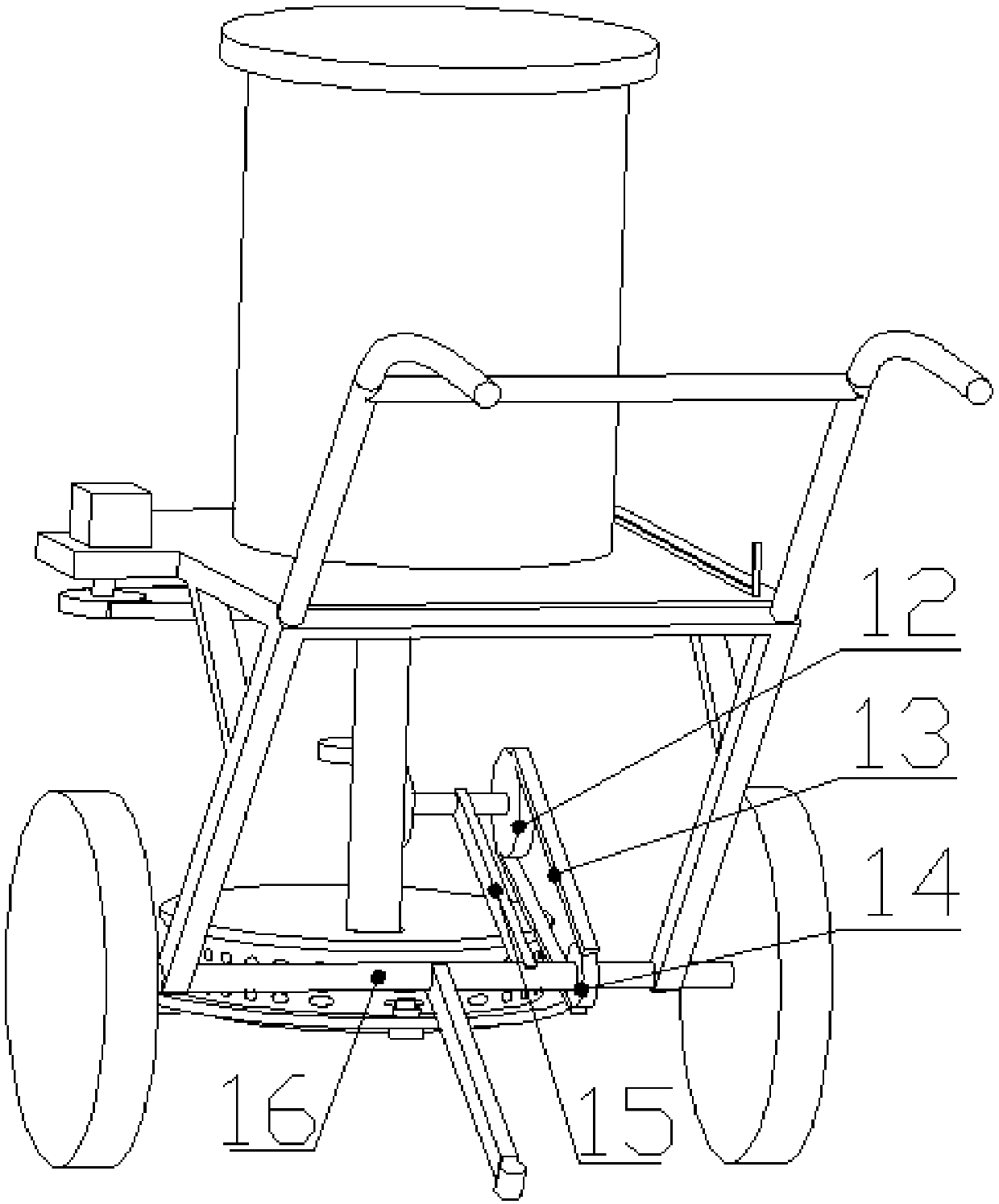
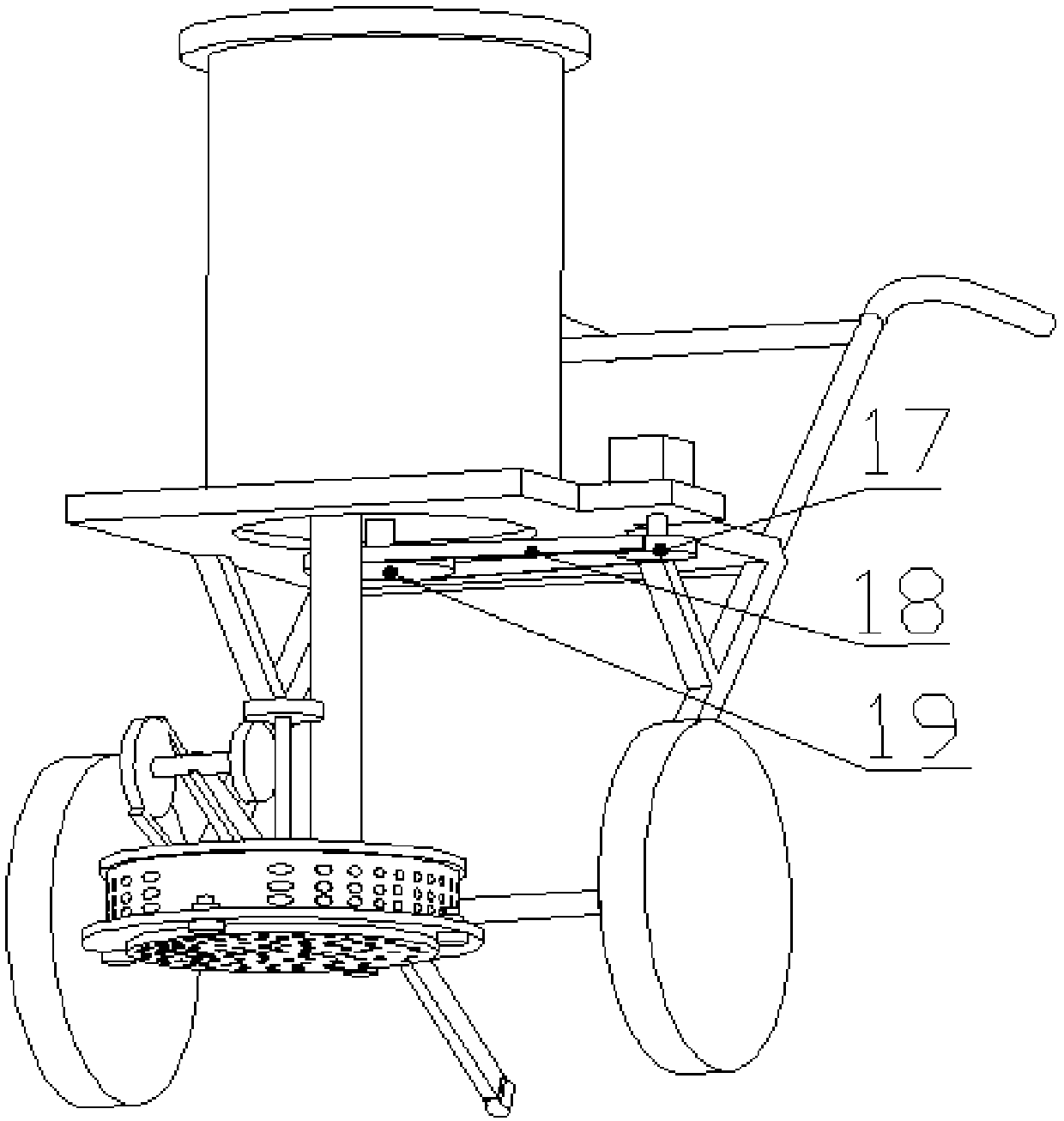
[0009] A centrifugal fertilizer application device for agricultural use is composed of handlebar 1, armrest rod 2, motor 3, ribs 4, wheels 5, balance rod 6, secondary storage barrel cover 7, driving bevel gear 8, Driven bevel gear 9, support plate 10, primary storage barrel 11, lower large sprocket 12, lower chain 13, lower small sprocket 14, rotating support rod 15, main rotating shaft 16, upper small sprocket 17, upper Chain 18, upper sprocket 19, rotating shaft 20, connecting plate 21, secondary storage barrel 22, chassis 23, connecting nut 24, primary storage barrel lid 25, spiral sheet 26, discharge tube 27, lower The material handle 28 and the inner rotating disk 29 are characterized in that: a handrail 2 is installed between the two handlebars 1, and the handlebar 1 is fixedly installed on the main rotating shaft 16 through bearings, on both sides of the main rotating shaft 16. Two wheels 5 are fixedly installed, the balance bar 6 is fixedly installed on the main rotatin...


PUM


Abstract

The invention discloses an agricultural centrifugal fertilizer-spreading device, and belongs to the technical field of the agricultural machinery. The agricultural centrifugal fertilizer-spreading device uses a two-stage storing mode, and is composed of a spiral-type beating mechanism and a rotation centrifugal fertilizer-spreading mechanism. The agricultural centrifugal fertilizer-spreading device is characterized in that a motor drives spiral blades on an inner rotating disk to be rotated through a transmission mechanism, a large piece of the chemical fertilizer is smashed, a main rotation shaft connected on a wheel drives a rotation shaft to be rotated through the transmission mechanism, the rotation shaft passes through a connecting plate and is connected with a two-stage storing tank, a lot of small holes are opened around the two-stage storing tank so as to spread the fertilizer smoothly, five connecting holes are uniformly opened in the connecting plate, and the range of spreading the fertilizer can be controlled by connecting the different holes. The agricultural centrifugal fertilizer-spreading device is capable of automatically beating a large piece of the chemical fertilizer, uniformly spreading the fertilizer by the centrifugal rotation tank, and changing the spreading range, and is suitable for the particle-shaped and powder-shaped fertilizer.

Description

Technical field [0001] The invention relates to an agricultural centrifugal fertilizer application device, specifically an agricultural centrifugal fertilizer application device that adopts a two-stage feeding mechanism, a spiral crushing mechanism and a rotary centrifugal fertilizer application mechanism. It belongs to the field of agricultural machinery. Background technique [0002] Recently, farmers need to spread chemical fertilizers in the fields during the busy season. The traditional way of spreading chemical fertilizers is to use pots to hold the fertilizer, and then grab the chemical fertilizer by hand and throw it. First, the spraying efficiency is low and the fertilizer can not be sprayed. Even, the second reason is that the corrosive effect of chemical fertilizers will hurt your hands. In recent years, some fertilizer spraying devices have emerged, but most of them are filled with storage buckets, and the fertilizer falls on the rotating disk driven by the wheels to ...

Claims


Application Information

Patent Timeline
Patent Type & Authority Patents(China)
IPC IPC(8): A01C17/00A01C15/12
CPCA01C15/12A01C17/001A01C17/008Y02P60/21
Inventor 鲍兆伟郑庆新张洪铭张坤
Owner 黑龙江省樱田农机制造有限公司
Learn More