Tensile integrated bionic knee joint

A technology of tensegrity and knee joints, which is applied in the field of bionic knee joints, can solve the problems of joint failure, poor impact absorption ability, high energy consumption for joint stability, and achieve the effect of improving stability

Active Publication Date: 2017-02-01
JILIN UNIV
View PDF8 Cites 16 Cited by
  • Summary
  • Abstract
  • Description
  • Claims
  • Application Information

AI Technical Summary

Problems solved by technology

[0007] The purpose of the present invention is to provide a tensegrity integral bionic knee joint in order to solve the problems of the rigid hinge joints used in the existing robots, such as easy friction, joint failure due to wear, high energy consumption for maintaining joint stability, and poor impact absorption ability.

Method used


Image

  • Tensile integrated bionic knee joint
  • Tensile integrated bionic knee joint
  • Tensile integrated bionic knee joint

Examples


Embodiment Construction

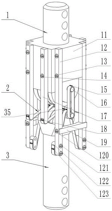
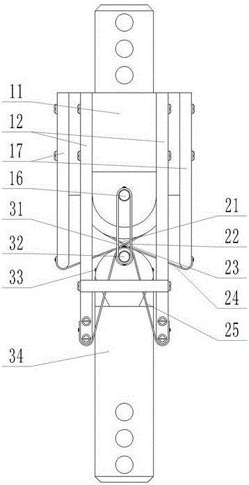
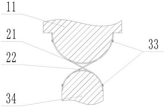
[0022] see figure 1 , figure 2 , image 3 and Figure 4 As shown, this embodiment includes a first rigid compression unit 1 , a cable unit 2 and a second rigid compression unit 3 .

[0023] The first rigid compression unit 1 is composed of the first rigid compression unit main body 11, the first support rod 12, the second support rod 17, the third support rod 19, and the fourth support rod 122. Two groups of symmetrically distributed The first support rod 12 is fixedly connected to the main body 11 of the first rigid compression unit through four sets of first screws 13; On the unit main body 11; a pair of symmetrically distributed third support rods 19 are fixed between the two groups of first support rods 12 by two pairs of fifth screws 120 to enhance the overall support rigidity; four evenly distributed fourth support rods 122 are fixedly connected with the first support rod 12 through sixth screws 121 respectively.

[0024] The cable unit 2 is composed of a first bio...


PUM


Abstract

The invention discloses a tensile integrated bionic knee joint which comprises a first rigid compression unit, a stay rope unit and a second rigid compression unit, wherein the first rigid compression unit is composed of a first rigid compression unit main body, a first support rod, a second support rod, a third support rod and a fourth support rod; the stay rope unit is composed of a first bionic cruciate ligament, a second bionic cruciate ligament, a bionic accessory ligament, a first stay rope and a second stay rope. According to the tensile integrated bionic knee joint, through the cooperative use of the bionic ligaments and other stay ropes, a rigid connecting shaft in the middle of the joint is avoided while realizing the movement of the joint on a sagittal plane, so that the friction and wearing between rigid bodies do not exist when the joint moves, and the service life of the joint is prolonged. Meanwhile the stay rope unit is made of rubber materials, has strong elasticity, can absorb a certain impact loads in the working process and improves the stability.

Description

technical field [0001] The invention relates to the technical field of mechanical bionic engineering, in particular to a bionic knee joint based on a tensegrity integral structure applicable to the fields of robots, prosthetics and the like. Background technique [0002] Research work on robots worldwide has been widely carried out, but at present almost all robot joints (hip joints, knee joints and ankle joints, etc.) are simplified and designed as hinged connections. Since the robot joints are often subjected to various types of loads such as tension and compression, shearing, bending and torsion during motion, driving and complex control are required to maintain the stability of the joint motion in real time. At the same time, since the hinge connection is mostly rigid , There is inevitably friction and impact between rigid bodies. Studies have shown that these may be important reasons for the complexity of the motion control system of this type of robot and the low energ...

Claims


Application Information

Patent Timeline
Patent Type & Authority Applications(China)
IPC IPC(8): A61F2/64A61F2/08B25J9/00B25J17/02
CPCA61F2/08A61F2/0811A61F2/64A61F2002/0817A61F2002/0847B25J9/0006B25J17/02
Inventor 钱志辉周亮任雷梁威任露泉
Owner JILIN UNIV
Why Eureka
Try Eureka