
Tool bar mechanism for turning machining of series of deep blind holes

A technology of deep blind holes and tool holders, which is applied in the direction of tool holders, etc., can solve problems such as insufficient clamping force, easy vibration of tool holders, and low processing efficiency, so as to reduce imbalance or instability and overcome tremors or instability , Improve the effect of machining accuracy

Active Publication Date: 2017-02-01
HUBEI SANJIANG SPACE XIANFENG ELECTRONICS&INFORMATION CO LTD
View PDF9 Cites 1 Cited by
  • Summary
  • Abstract
  • Description
  • Claims
  • Application Information

AI Technical Summary

Problems solved by technology

In addition, due to the mechanical clamping method of two halves of the tool rod, the clamping time is long when clamping, which makes the production preparation time for each processing long, and the processing is often due to improper tooling, low processing quality and extremely low processing efficiency; In particular, due to machining accuracy problems when mechanically clamping the tool bar, the clamping device and the tool bar are in line contact, the clamping force is not enough, and the tool bar is prone to vibration during processing, which has a great impact on the machining accuracy of blind holes, which will make There is a large error in the machining accuracy of blind holes

Method used


Image

  • Tool bar mechanism for turning machining of series of deep blind holes
  • Tool bar mechanism for turning machining of series of deep blind holes
  • Tool bar mechanism for turning machining of series of deep blind holes

Examples


Embodiment Construction

[0024] In order to make the object, technical solution and advantages of the present invention clearer, the present invention will be further described in detail below in conjunction with the accompanying drawings and embodiments. It should be understood that the specific embodiments described here are only used to explain the present invention, not to limit the present invention. In addition, the technical features involved in the various embodiments of the present invention described below can be combined with each other as long as they do not constitute a conflict with each other.

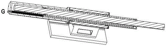
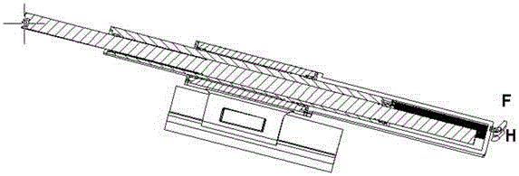
[0025] A tool bar mechanism for turning blind holes constructed according to an embodiment of the present invention is used for turning a series of large deep blind holes, and the tool bar mechanism can adapt to series of large deep blind holes with different hole depths and diameter Continuous machining of blind holes.

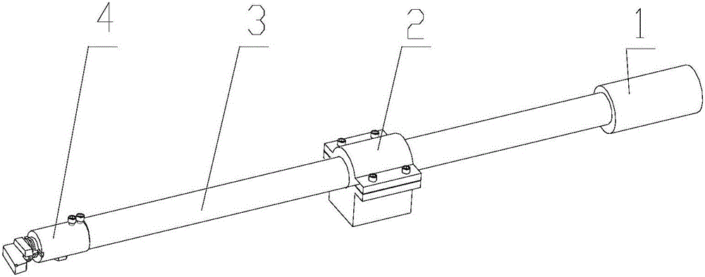
[0026] Such as Figure 2-4 As shown, the cutter bar mechanism includes a...


PUM


Abstract

The invention discloses a tool bar mechanism for turning machining of a series of deep blind holes. The tool bar mechanism comprises a tail seat fixedly connected with a machine tool, a telescopic rod which is arranged in an axial through hole in a body, penetrates through a through hole in a tail seat body and extends to the machining front end, a first clamping mechanism being arranged on the end surface, through which the telescopic rode extends out, of the tail seat body, a tool bar which is coaxially arranged in a through hole of the telescopic rod in a sleeving manner, extends to the machining end and is used for performing boring operation, a second clamping mechanism being arranged on the end surface, through which the tool bar extends out, of the telescopic rod and being used for locking the tool bar, and a balance oil cylinder for storing or discharging oil to balance the weight so as to match and balance the unbalance of the tool bar mechanism in the axial direction due to the telescoping of the telescopic rod and / or the tool bar in the axial direction. The tool bar mechanism disclosed by the invention can realize quick adjustment of the length of the tool bar; the rigidity of the tool bar serving as a fixture is improved, the influence on the blind hole machining precision due to the vibration of the tool bar during machining is avoided; and accurate balancing of the weight of the tool bar can be automatically realized.

Description

technical field [0001] The invention relates to the field of turning processing, in particular to a cutter bar mechanism for blind hole turning. Background technique [0002] Blind hole processing is a common processing method in mechanical cutting, especially for some large parts, through the processing of multiple large deep blind holes, the diameter of the blind hole can be changed from The depth can reach 800~2500mm. [0003] For blind hole machining, machining by lathe cutting is a common way. When processing, one option is to use figure 1 The tool bar mechanism with the structure shown in the figure clamps the tool for processing, such as figure 1 As shown, the tool bar 3 is supported by the support 2, and one end is provided with a counterweight 1 to ensure the force balance of the tool bar on the support 2, and the tool is clamped on the pneumatic quick-change mechanism 4 at the other end of the tool bar 3 for workpiece On-line detection and processing of deep b...

Claims


Application Information

Patent Timeline
Patent Type & Authority Applications(China)
IPC IPC(8): B23B29/04
CPCB23B29/04
Inventor 王晓兵钟家坪汪学斌
Owner HUBEI SANJIANG SPACE XIANFENG ELECTRONICS&INFORMATION CO LTD
Learn More