Independently suspended front drive front axle assembly

A front axle assembly, independent suspension technology, applied in the steering mechanism, steering rod, wheel hub, etc., can solve the problems of difficult layout of the battery box of the new energy electric bus, unfavorable speed and cruising range of the electric bus, affecting the stability of the vehicle, etc. , to achieve the effect of facilitating the overall layout, improving the ride comfort, and improving the suspension function

Inactive Publication Date: 2017-02-01
通天汽车桥(天津)有限公司
View PDF6 Cites 6 Cited by
  • Summary
  • Abstract
  • Description
  • Claims
  • Application Information

AI Technical Summary

Problems solved by technology

[0004] 1. The front rear drive needs to install a transmission shaft between the engine and the rear axle to transmit power. The installation of the transmission shaft not only increases the weight of the vehicle and affects the overall layout, but more importantly, it has a great impact on the battery box layout of the new energy electric bus. great difficulty;
[0005] 2. The front and rear drive require a larger and longer transmission shaft, which will increase the weight of the vehicle and be detrimental to the speed and cruising range of the electric bus;
[0006] 3. The front and rear drive will cause the floor of the vehicle to rise, which in turn will increase the center of gravity of the car and affect the stability of the car.

Method used


Image

  • Independently suspended front drive front axle assembly
  • Independently suspended front drive front axle assembly
  • Independently suspended front drive front axle assembly

Examples


Embodiment Construction

[0022] Further illustrate the present invention below in conjunction with embodiment and accompanying drawing.

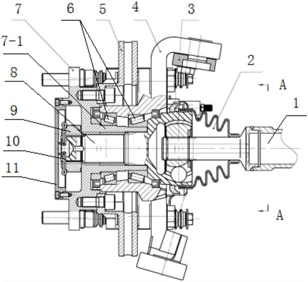
[0023] Such as figure 1 In the shown embodiment, the power of the engine is transmitted through the reducer and the differential to the two transmission half shafts 1, and the drive shaft assembly 2 at the front end of each transmission half shaft is provided with a transmission spline shaft 8, and each transmission spline shaft 8 is respectively Engage with the spline sleeve 7-1 of the left and right front wheel hub 7.

[0024] The screw rod at the front end of each transmission spline shaft 8 is provided with a lock nut 9 fastened to one end of the spline sleeve, and the lock nut 9 and the screw rod at the front end of the transmission spline shaft are provided with a stop cotter pin 10 .

[0025] The front end of the sleeve type steering knuckle 4 is provided with a bearing seat that is sleeved on the spline sleeve 7-1 of the front wheel hub, and a pair of taper...


PUM


Abstract

The invention discloses an independently suspended front drive front axle assembly. The front end of each transmission semi-axle is provided with a front drive shaft assembly. A sleeve type steering knuckle is installed at the front end of each front drive shaft assembly in the radial direction, and a transmission spline shaft is arranged at the front end of each front drive shaft assembly in the axial direction. Each transmission spline shaft is engaged with a spline sleeve on the inner side of a left front wheel hub and a spline sleeve on the inner side of a right front wheel hub. The front end of each transmission spline shaft is provided with a screw rod which is matched with a locking nut fastened to one end of the corresponding spline sleeve. Each spline sleeve is sleeved with a bearing pedestal, and each bearing pedestal is arranged at the front end of the corresponding steering knuckle. Conical roller bearings are arranged between the bearing pedestals and the spline sleeves in pairs. A brake disc is fixed to the inner side of the front wheel hub. Brake assemblies in friction joint with the brake disc are symmetrically arranged on the brake disc front and back in the transverse direction. The brake assemblies are fixed to the two sides of a flange plate. Brakes are hydraulic drive brakes. As for a front drive mechanism, an original transmission shaft structure for connecting an engine with a rear wheel is omitted, the height of a chassis of a large/medium-sized passenger vehicle can be reduced properly, meanwhile, the weight of the passenger vehicle is reduced, and running stability is improved advantageously.

Description

technical field [0001] The invention relates to the field of automobile front axles, in particular to an independent suspension type front drive front axle assembly. Background technique [0002] The vehicle front axle assembly in the prior art mainly includes the front axle beam, the real shaft steering knuckle, the kingpin, the steering knuckle arm, the steering trailing arm, the steering tie rod, the hub bearing, the front wheel hub, the brake disc, the air brake, the front Axle locknuts, cotter pins and hub caps. The cross beam of the front axle is connected to the vehicle body through the suspension components such as the steering knuckle and the leaf spring through the kingpin to carry the weight of the vehicle body. The real shaft steering knuckle is connected with the front axle beam through the king pin; the wheel is supported through the connection between the hub bearing, the front axle lock nut and the cotter pin and the front wheel hub; the wheel steering is re...

Claims


Application Information

Patent Timeline
Patent Type & Authority Applications(China)
IPC IPC(8): B60B27/00B62D7/18
CPCB60B27/0026B60B27/0052B62D7/18
Inventor 田永生刘向东董文光石德泉李政山穆牧之
Owner 通天汽车桥(天津)有限公司
Why Eureka
Try Eureka