
Brake control device for rail transit vehicle and electro-pneumatic hybrid braking control method of brake control device

A rail transit vehicle and braking control technology, applied in the direction of braking transmission, brakes, railway vehicles, etc., can solve the problems of reduced braking force of the whole train, reduced safety of rail transit vehicles, less braking force, etc., and meets the requirements for use. Good, reduce the braking distance is too long, prevent the effect of wheel abrasion

Active Publication Date: 2017-02-01
NANJING CRRC PUZHEN HAITAI BRAKE EQUIP CO LTD
View PDF12 Cites 32 Cited by
  • Summary
  • Abstract
  • Description
  • Claims
  • Application Information

AI Technical Summary

Problems solved by technology

[0003] According to the above description, it is not difficult to see that the current rail vehicle brake control device and its electro-pneumatic hybrid brake control have the following defects: the traction control system and the brake control system of the prior art are relatively independent. When the actual applied value of electric brake of a certain car is less than the applied value of electric brake, the whole braking force will be less, but the train will not redistribute the braking force
Therefore, if one of the rail transit vehicles makes the actual application value of the electric brake less than the application value due to some reasons of the traction control system, the braking force of the whole train will decrease, resulting in the extension of the braking distance beyond the designed value. value, thereby reducing the safety of rail transit vehicles

Method used


Image

  • Brake control device for rail transit vehicle and electro-pneumatic hybrid braking control method of brake control device
  • Brake control device for rail transit vehicle and electro-pneumatic hybrid braking control method of brake control device

Examples


Embodiment Construction

[0039]The present invention will be described in detail below in conjunction with the accompanying drawings and specific embodiments.

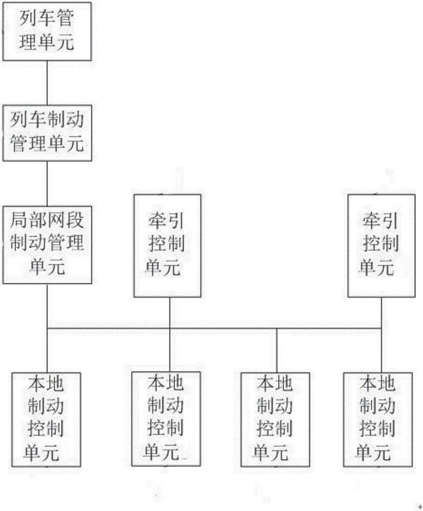
[0040] Such as figure 1 As shown, the brake control device of the rail transit vehicle includes a train management unit, a train brake management unit, a local network segment brake management unit, a traction control unit and a local friction brake control unit, and the train management unit is connected to the train system The train management unit is connected, and the train management unit issues braking instruction information to the train braking management unit;

[0041] The train braking management unit is connected to the local network segment braking management unit, and the train braking management unit collects the braking instruction information transmitted by the train management unit and the available maximum electric braking force transmitted by the local network segment braking management unit and frictional braking force val...


PUM


Abstract

The invention discloses a brake control device for a rail transit vehicle and an electro-pneumatic hybrid braking control method of the brake control device. A train braking management unit receives commands from a train management unit to calculate percentage signals of braking force needing to be produced by electric braking and percentage signals of braking force needing to be produced by friction braking respectively; a local network segment braking management unit collects the percentage signals transmitted by the train braking management unit and transmits electric braking force percentage signals to traction control units, and recalculates percentage signals of friction braking force needing to be produced by local friction brake control units according to a maximum available electric braking force value transmitted by the traction control units and an actually applied electric braking force value; the traction control units are used for applying electric braking force according to electric braking percentage signals; and the local friction brake control units are used for applying friction braking force according to friction braking percentage signals. Through the adoption of the brake control device and the electro-pneumatic hybrid braking control method thereof disclosed by the invention, the risk of an overlong braking distance due to insufficient braking force can be reduced, and the economical efficiency is good.

Description

technical field [0001] The invention relates to the field of train braking, in particular to a braking control device for rail transit vehicles and an electro-pneumatic hybrid braking control method thereof. Background technique [0002] At present, the brake control system used on rail transit vehicles works like this: First, each traction control unit and each local friction brake control unit calculates the braking capacity available for itself, and sends this information to the local network segment brake management The local network segment braking management unit summarizes the information and sends it to the train braking management unit; then, the train braking management unit receives the train braking command to calculate the braking force required by the entire train, and according to the local network segment control According to the information sent by the brake management unit, these braking forces are preferentially allocated to the electric braking. If the el...

Claims


Application Information

Patent Timeline
IPC IPC(8): B60L7/26B60T13/66
CPCB60L7/26B60L2200/26B60T13/665
Inventor 杨俊孙环阳罗飞平杨正专
Owner NANJING CRRC PUZHEN HAITAI BRAKE EQUIP CO LTD
Learn More