Method and system for protecting trains against collisions

A technology for collision protection and trains, applied in the direction of railway vehicle wheel guards/buffers, railway car body parts, transportation and packaging, etc., can solve problems such as uncontrollable damage to vehicles, differences in energy absorption characteristics, etc., to improve safety, Stable energy-absorbing properties and extended length

Active Publication Date: 2017-02-01
CENT SOUTH UNIV
View PDF7 Cites 10 Cited by
  • Summary
  • Abstract
  • Description
  • Claims
  • Application Information

AI Technical Summary

Problems solved by technology

In addition, under different collision conditions, the energy absorption characteristics of the structure show great differences, which can easily lead to uncontrollable damage of the vehicle during the collision

Method used


Image

  • Method and system for protecting trains against collisions
  • Method and system for protecting trains against collisions
  • Method and system for protecting trains against collisions

Examples


Embodiment 1

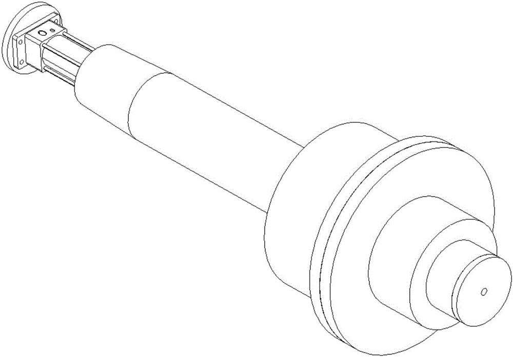
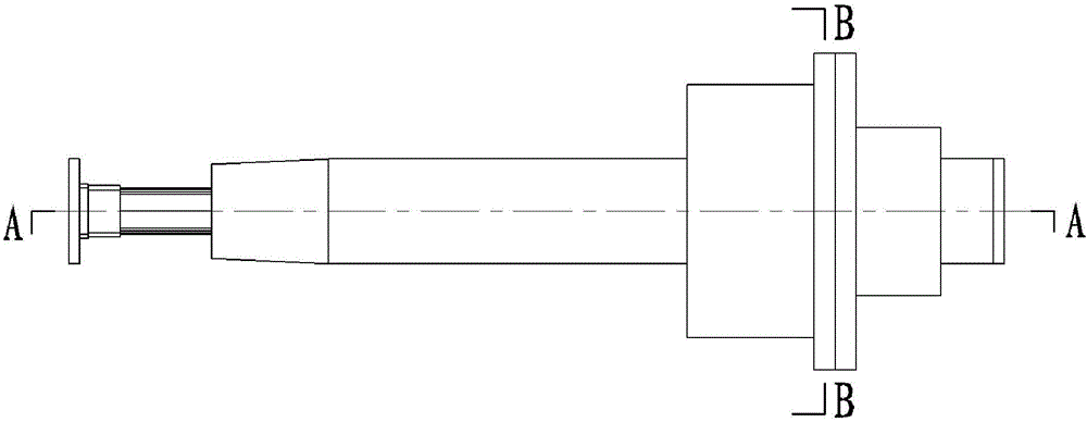
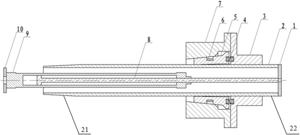
[0051] Figure 1-9 is the energy absorbing device structure of Embodiment 1 of the present invention, wherein Figure 1~4 is the state where the energy-absorbing tube shrinks in the car body when the train is running normally, Figure 5-8 It is a structural diagram of the energy-absorbing device outside the vehicle body with the energy-absorbing tube stretched out before the collision accident. After the collision accident, the energy-absorbing tube will change from Figure 7 Extrude in the inner via hole 54 that the four block sleeves 5 shown together form, specifically Figure 7 The middle energy-absorbing tube is extruded from right to left, and the inner diameter of the energy-absorbing tube after collision extrusion becomes smaller and absorbs energy.

[0052] Specifically, such as Figure 1~4 As shown, when the train is running normally, the energy-absorbing tube 2 shrinks inside the car body under the pulling force of the cylinder piston rod 8, and the four limit sl...

Embodiment 2

[0055] Figures 10-14 is the energy absorbing device structure of Embodiment 2 of the present invention, wherein Figure 10-12 is the state where the energy-absorbing tube shrinks in the car body when the train is running normally, Figure 13 It is a structural diagram of the energy-absorbing device outside the vehicle body with the energy-absorbing tube stretched out before the collision accident. After the collision accident, the energy-absorbing tube will change from Figure 13 Extrude in the inner via hole 54 that the four block sleeves 5 shown together form, specifically Figure 13 The middle energy-absorbing tube is extruded from right to left, and the inner diameter of the energy-absorbing tube after collision and extrusion is reduced to absorb energy.

[0056] specifically, Figure 10 Shown is the structure schematic diagram of the automatic retractable energy-absorbing device of the limit sleeve 5, the positioning ring 6 is connected with the movable pin shaft 12,...

Embodiment 3

[0058] In the present invention, when the train is running normally, the structure of the train collision protection system is as follows: Figure 15 In the structure shown, the anti-climbing tooth at the end of the energy-absorbing tube is located closer to the car body (passenger compartment) than the coupler. After the instrument or manpower recognizes the train collision danger signal, the telescopic drive structure actively pushes the energy-absorbing tube and the anti-climbing gear to a position away from the car body. After the energy-absorbing tube is pushed out, the structure of the train collision protection system is as follows Figure 16 In the shown structure, the anti-climbing tooth at the end of the energy-absorbing tube is located far away from the car body compared with the coupler. For example, the coupler stretches out 0.5m in front of the car body, while the anti-climbing teeth stretch out 1m in front of the car body. When the train collides, the anti-climb...


PUM


Abstract

The invention provides a method and system for protecting trains against collisions. According to the method and system, the mode that a train hook energy absorbing structure, an anti-crawling energy absorbing structure and a train deformation energy absorbing structure act successively is not adopted any more, but the anti-crawling energy absorbing structure acts firstly. The length of an energy absorbing pipe in the system for protecting the train against collisions is not limited by the position of train hooks any more, so that the length of the energy absorbing pipe is significantly increased, energy absorbed by the anti-crawling energy absorbing structure can be significantly improved compared with the prior art, more collision kinetic energy can be dissipated when collisions happen, and the safety of the trains is remarkably improved. According to the anti-crawling energy absorbing structure, the energy absorbing ratio is large, the effective travel is long, the influence of load conditions on deformation is small, and the energy absorbing characteristic under different collision conditions is stable. When the energy absorbing structures are triggered by accident, a telescopic drive structure can drive the energy absorbing pipe to retract back into a train body conveniently in a direct one-key control mode, and the effect that the trains can be normally coupled through the train hook is ensured.

Description

technical field [0001] The invention belongs to the technical field of rail train safety protection, and in particular relates to a train collision protection method and a train collision protection system. Background technique [0002] With the continuous improvement of train speed, the requirements for train crashworthiness are also getting higher and higher. When designing the crashworthy structure of a rail vehicle, due to the limited deformation space at the end of the rail vehicle, it is necessary to fully consider the matching of the longitudinal stiffness of the end of the train and the appearance size of the existing car body without affecting the running performance and appearance of the vehicle. To meet the requirements of its collision safety, this greatly restricts the external dimensions of the designed energy-absorbing structure, and affects the energy absorption and energy-absorbing efficiency of the energy-absorbing structure. [0003] The design of the cra...

Claims


Application Information

Patent Timeline
Patent Type & Authority Applications(China)
IPC IPC(8): B61F19/04
CPCB61F19/04
Inventor 高广军关维元
Owner CENT SOUTH UNIV
Why Eureka
Try Eureka