A color steel tile roof edge and corner fixture based on cam structure
A technology of color steel tiles and fixtures, which is applied to roofs, roofs, and roof coverings that use flat/curved panels. It can solve the problem that the corners are not fixedly connected to the beams, the roof loses wind and rain, and there is no roof fixture. problem, to achieve the effect of compact structure, simple structure and low cost
- Summary
- Abstract
- Description
- Claims
- Application Information
AI Technical Summary
Problems solved by technology
Method used
Image
Examples
Embodiment 1
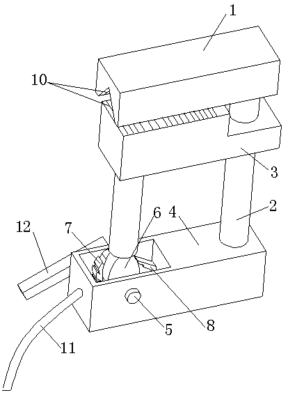
[0027] like figure 1 , figure 2 , as shown in Figure 3, in the present embodiment, a color steel tile roof corner clamp based on a cam structure includes an upper clamp 1 corresponding to the roof beam, a connecting rod 2 connected to the upper clamp 1, a sliding connection in the connection The lower clamp 3 on the rod 2 also includes a driving part fixedly connected to the connecting rod 2 and used to drive the lower clamp 3 to slide up and down. The upper clamp 1 and the lower clamp 3 are used in conjunction to fix the corners of the color steel tile and the beam together.
[0028] With the above structure, the clamping of the corners of the color steel tiles can be realized when the color steel tiles are installed, preventing the corners from falling off when being blown by the wind, enhancing the stability of the color steel tiles after installation, and improving the performance of the present invention. Practicality; and the present invention has simple structure, lo...
Embodiment 2
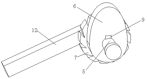
[0030] This embodiment is further limited on the basis of the above embodiments. In this embodiment, the drive part includes a housing 4 mounted on the connecting rod 2, a rotating shaft 5 connected to the housing 4 and facing the inner space of the housing 4, A driving block 6 connected to the rotating shaft 5 and installed in the housing 4, an operating rod 12 installed on the rotating shaft 5 and located outside the housing 4, the driving block 6 is connected to the lower clamp 3 and drives the lower clamp 3 on the connecting rod 2 To slide up and down, the above-mentioned drive block 6 is a cam, and the cam is connected to the rotating shaft 5 through a key 9 .
[0031] With the above structure, the operating rod 12 is used to drive the cam to rotate around the rotating shaft 5. During this process, due to the special structure of the cam, the lower clamp 3 connected to the transmission will move up and down under the action of the cam to realize clamping. The operation pr...
Embodiment 3
[0034] This embodiment is further improved on the basis of the above embodiments. In this embodiment, the drive part also includes a ratchet 7 that is installed on the rotating shaft 5 and rotates synchronously with the rotating shaft 5, and is arranged on the casing 4 and is used to cooperate with the ratchet 7. A pawl 8 that cooperates to limit the rotation of the ratchet 7 .
[0035] With the above structure, when the present invention is installed, under the action of the ratchet 7 and the pawl 8, the rotating shaft 5 of the present invention will no longer rotate, so that the lower clamp 3 will not be automatically displaced after reaching the installation position situation, thereby enhancing the reliability of the present invention.
PUM
 Abstract
Description
Claims
Application Information
 - R&D
- Intellectual Property
- Life Sciences
- Materials
- Tech Scout
- Unparalleled Data Quality
- Higher Quality Content
- 60% Fewer Hallucinations
Browse by: Latest US Patents, China's latest patents, Technical Efficacy Thesaurus, Application Domain, Technology Topic, Popular Technical Reports.
© 2025 PatSnap. All rights reserved.Legal|Privacy policy|Modern Slavery Act Transparency Statement|Sitemap|About US| Contact US: help@patsnap.com


