Ball valve upstream and downstream seal control method and control system

A technology of sealing control and control system, which is applied in the fields of hydropower generation, engine components, machines/engines, etc., can solve the problems of low maintenance efficiency, long return time of units, hidden safety hazards, etc., so as to improve safety and efficiency, shorten return Backup time, avoidance of investment and the effect of dismantling

Active Publication Date: 2017-02-01
STATE GRID CORP OF CHINA +2
View PDF2 Cites 2 Cited by
  • Summary
  • Abstract
  • Description
  • Claims
  • Application Information

AI Technical Summary

Problems solved by technology

However, the inspection and sealing mechanical locking bolt can only be put into operation when the maintenance personnel enter the downstream flow channel of the ball valve for maintenance, and there are still certain potential safety hazards
Moreover, it is time-consuming and labor-intensive to invest 12 inspection seal mechanical locking bolts on the upstream side of the ball valve. Even if two people operate at the same time, it will take about 2 hours to complete; The sealing mechanical locking bolts are disassembled; resulting in low maintenance efficiency and increased unit back-up time
Therefore, the ball valve sealing control method and control system in the existing pumped storage power station have the problems of unsatisfactory safety, low maintenance efficiency and long unit back-up time when the unit is overhauled.

Method used


Image

  • Ball valve upstream and downstream seal control method and control system

Examples


Embodiment Construction

[0017] The present invention will be further described below in conjunction with the examples, but not as a basis for limiting the present invention.

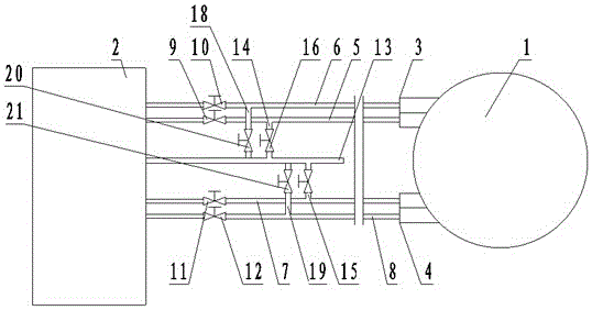
[0018] Example. A ball valve upstream and downstream sealing control method, such as figure 1 As shown, the method is between the ball valve pressure oil tank 1 and the sealing control cabinet 2, the maintenance seal input cavity pipeline 5, the maintenance seal exit cavity pipeline 6, the working seal input cavity pipeline 7 and the working seal exit cavity pipeline 8 are provided with a first valve 9, a second valve 10, a third valve 11 and a fourth valve 12; and the fourth valve 12 to manually shield and seal the control cabinet 2, thereby preventing the unit from rotating and improving the safety and efficiency of the unit maintenance.

[0019] After the first valve 9, the second valve 10, the third valve 11 and the fourth valve 12 are closed, the fifth valve 16 and the sixth valve 17 are manually opened, and the sealing ...


PUM


Abstract

The invention discloses a ball valve upstream and downstream seal control method and a control system. According to the method, each of an overhaul seal entering cavity pipeline, an overhaul seal exiting cavity pipeline, a working seal entering cavity pipeline and a working seal exiting cavity pipeline located between a ball valve pressure oil tank and a seal control cabinet is provided with a first valve, a second valve, a third valve and a fourth valve; and during regular check and defect elimination of a unit, the seal control cabinet is manually shielded through closing the first valve, the second valve, the third valve and the fourth valve. The control system comprises the ball valve pressure oil tank, the seal control cabinet, the overhaul seal entering cavity pipeline, the overhaul seal exiting cavity pipeline, the working seal entering cavity pipeline and the working seal exiting cavity pipeline, and each pipeline is provided with the first valve, the second valve, the third valve and the fourth valve. When being used for overhauling the unit, the ball valve ball valve upstream and downstream seal control method and the control system not only can be used for improving the safety, but also have the advantages of high overhaul efficiency, short unit exiting time, low manpower cost and high generating capacity.

Description

technical field [0001] The invention relates to an upstream and downstream sealing control method and control system of a ball valve, in particular to a control method and a control system for an upstream and downstream sealing of a ball valve used in a pumped storage power station. Background technique [0002] In the existing pumped storage power station, the sealing control cabinet is generally used to control the sealing of the main water inlet valve (ball valve), so that the sealing throw-in and withdrawal circuit of the main water inlet valve is a fully automatic circuit, which is convenient for the sealing throw-in of the main water inlet valve. Back off automatic control. However, in the process of regular inspection or defect elimination of the unit, the reliability of the existing sealing control method is poor, especially in the case of pressure relief of the ball valve pressure oil tank, etc., the seal on the ball valve pressure oil tank has a tendency to automat...

Claims


Application Information

Patent Timeline
Patent Type & Authority Applications(China)
IPC IPC(8): F03B13/06F03B15/00F03B11/00
CPCF03B11/00F03B13/06F03B15/00Y02E10/20Y02E60/16
Inventor 张飞何铮丁光赵志文王龙
Owner STATE GRID CORP OF CHINA
Why Eureka
Try Eureka