
Automatic control method of cooling capacity of outer cooling unit

A technology of cooling capacity and unit, applied in the direction of engine control, pump control, machine/engine, etc., can solve the problems of difficult to accurately adjust the cooling capacity of external cooling, smoothly control the temperature of the cooled medium, and reduce the service life of the fan, so as to prolong the service life. The effect of life, adjustment range optimization, and power consumption reduction

Active Publication Date: 2017-02-01
CHANGZHOU BORI ELECTRIC POWER AUTOMATION EQUIP +1
View PDF5 Cites 11 Cited by
  • Summary
  • Abstract
  • Description
  • Claims
  • Application Information

AI Technical Summary

Problems solved by technology

At present, the heat dissipation technology of multiple sets of non-frequency conversion fans is usually used, and the cooling capacity of the water cooling system is controlled by adjusting the start and stop of multiple sets of non-frequency conversion fans. Since the cooling capacity adjustment steps of multiple sets of non-frequency conversion fans are large, it is difficult to accurately adjust the overall cooling of the external cooling system. Capacity, which is not conducive to smooth control of the temperature of the cooled medium, and frequent start and stop of non-variable frequency fans will easily reduce the service life of the fans

Method used


Image

  • Automatic control method of cooling capacity of outer cooling unit
  • Automatic control method of cooling capacity of outer cooling unit
  • Automatic control method of cooling capacity of outer cooling unit

Examples


Embodiment Construction

[0026] In order to make the content of the present invention more clearly understood, the present invention will be further described in detail below based on specific embodiments and in conjunction with the accompanying drawings.

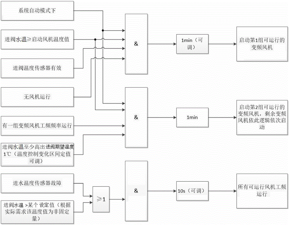
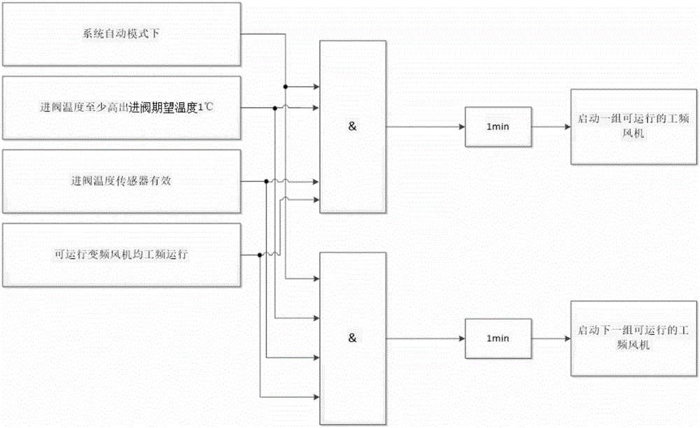
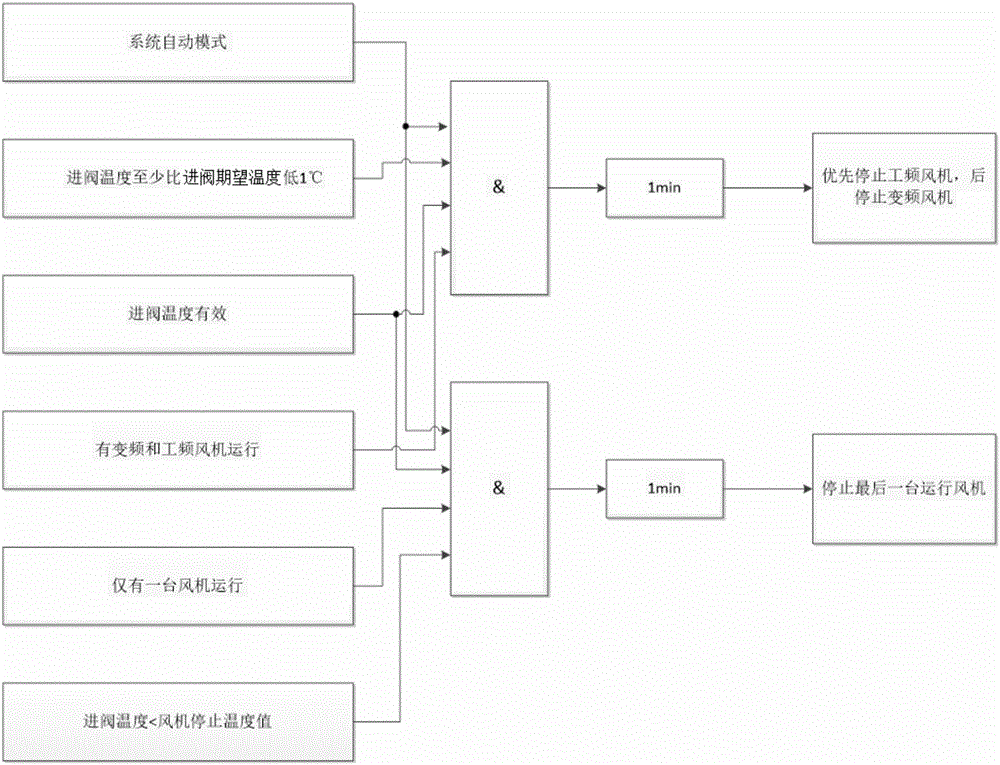
[0027] Such as Figure 1 to Figure 5 As shown, an automatic control method for the cooling capacity of an external cooling fan group, the external cooling fan group includes M frequency conversion fans and N power frequency fans, and the frequency conversion fans and power frequency fans are respectively controlled by logic circuits to start and stop; the automatic The control method includes a starting step and a stopping step;

[0028] The starting step: comparing the inlet valve water temperature with the inlet valve expected temperature, when the inlet valve water temperature is higher than the inlet valve expected temperature, start the variable frequency fan and the power frequency fan through the logic circuit;

[0029] The stopping step: c...


PUM


Abstract

The invention discloses an automatic control method of the cooling capacity of an outer cooling unit. The outer cooling unit comprises M variable-frequency draught fans and N power frequency draught fans. The variable-frequency draught fans and the power frequency draught fans are controlled by logical circuits to be started or stopped. The automatic control method comprises the starting step and the stopping step; in the starting step, a valve inlet water temperature is compared with a valve inlet preferred temperature, and when the valve inlet water temperature is higher than the valve inlet preferred temperature, the variable-frequency draught fans and the power frequency draught fans are started through the logic circuits; and in the stopping step, the valve inlet water temperature is compared with the valve inlet preferred temperature, and when the valve inlet water temperature is lower than the valve inlet preferred temperature, the variable-frequency draught fans and the power frequency draught fans are stopped through the logic circuits. According to the automatic control method of the cooling capacity of the outer cooling unit, through the start and stop control over the M variable-frequency draught fans and the N power frequency draught fans and the comparison between the real-time water temperature and the valve inlet preferred temperature, the outer cooling heat exchange capacity is adjusted; and in this way, the power consumption is lowered, smooth adjustment of the outer cooling heat exchange capacity is guaranteed, and the adjustment amplitude of the outer cooling capacity is optimized.

Description

technical field [0001] The invention relates to an automatic control method for the cooling capacity of an external cooling fan unit, belonging to the technical field of air cooling. Background technique [0002] The electric power industry currently has many electrical equipment composed of high-power power electronic semiconductor components, such as thyristor converter valves and IGBT converter valves, which are widely used in engineering fields such as direct current transmission. A closed circulating water cooling system is required to cool semiconductor components, and the closed water cooling system is usually water (inner)-water (outer) heat exchange or water (inner)-air (outer) heat exchange. In the water-air heat exchange process, due to the large amount of heat exchange required, multiple sets of external cooling fans are usually configured to cool the internal water. At the same time, due to the constant changes in the heat generated by the cooled semiconductor ...

Claims


Application Information

Patent Timeline
Patent Type & Authority Applications(China)
IPC IPC(8): F04D27/00H05K7/20
CPCH05K7/20209F04D27/00F05D2270/303F05D2270/706
Inventor 陈宇曦高晟辅徐偲喆黄海进
Owner CHANGZHOU BORI ELECTRIC POWER AUTOMATION EQUIP
Learn More