Multifunctional movable retaining wall test device

The technology of a test device and movable retaining wall is applied in the field of multifunctional movable retaining wall test device, which can solve the problems of single test conditions, high cost, and inability to change the operating space of the model box, and achieve the effect of easy operation and reduced labor intensity

Active Publication Date: 2017-02-01
ZHENGZHOU UNIV
View PDF4 Cites 5 Cited by
  • Summary
  • Abstract
  • Description
  • Claims
  • Application Information

AI Technical Summary

Problems solved by technology

However, the existing test conditions are single, and the main problems of the device for simulating the movement of the retaining wall are: the displacement mode is single, such as most of them can only simulate the translational displacement mode; for some devices that can perform the rotational displacement mode, due to the device itself Structural problems, the rotation angle of the movable retaining wall is very small, which cannot meet the large-angle rotation simulation experiment of the movable retaining wall; it is difficult to realize the active and passive earth pressure research in the same model box; the operating space of the model box cannot be changed to carry out the retaining wall under various conditions Model test of earth pressure; the existing equipment has the characteristics of high cost and few functions

Method used


Image

  • Multifunctional movable retaining wall test device
  • Multifunctional movable retaining wall test device
  • Multifunctional movable retaining wall test device

Examples


Embodiment Construction

[0025] The technical solutions of the present invention will be described in further detail below through specific implementation methods.

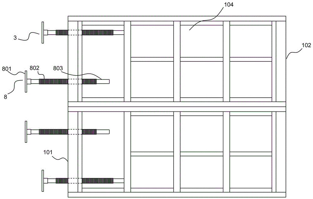
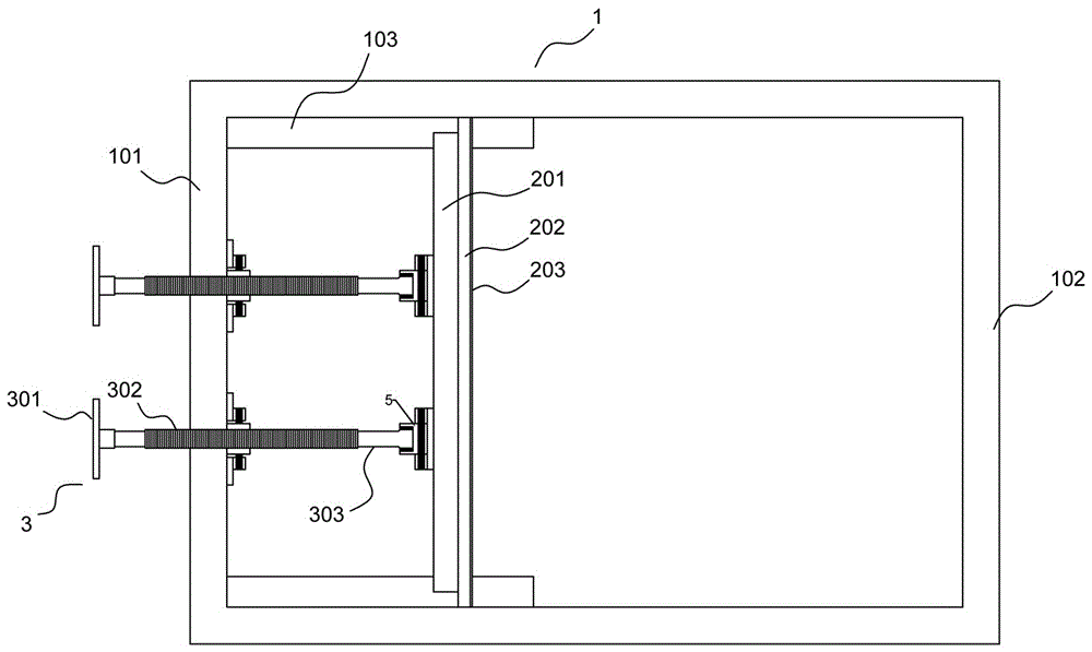
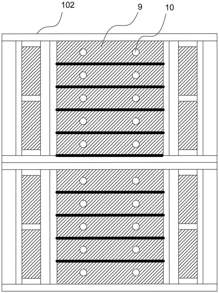
[0026] A kind of embodiment of multifunctional movable retaining wall test device, such as Figure 1-8 As shown, including model box 1 and movable retaining wall 2, model box 1 comprises model box frame, and the middle rear portion of the left and right sides of model box frame all is fixed with sidewall steel plate 104, and the rear end 102 of model box frame passes bolt (figure Not shown in the figure) a plurality of back wall steel plates 9 can be disassembled, and each back wall steel plate 9 is spliced ​​to form an unearthed plate that is convenient for entering and unearthed. In the example, the handle is a bolt welded on the rear wall steel plate, and the upper and lower parts of the front end 101 of the model box frame are provided with displacement control screw mechanisms. Displacement control screw mechanism, at least one row ...


PUM


Abstract

The invention provides a multifunctional movable retaining wall test device comprising a model box and a movable retaining wall. Displacement control screw mechanisms are arranged on the upper and lower parts of the front end of a model box frame. At least one row of auxiliary bearing screw mechanisms is arranged in the middle of the front end of the model box frame. Bearing seats are arranged in a pitch rotation way at positions of the movable retaining wall corresponding to through holes. A bearing used for inserting and fixing a corresponding displacement control screw is arranged inside each bearing seat. Grooves used for being in movable insertion fit with auxiliary bearing screws are arranged at positions of the movable retaining wall corresponding to auxiliary bearing nuts. According to the multifunctional movable retaining wall test device of the invention, through multi-stage alternate fine adjustment, namely, adjusting the auxiliary bearing screws first and then adjusting the displacement control screws and repeating the steps, test of different displacements and displacement modes needed is realized. The multifunctional movable retaining wall test device can realize active and passive earth pressure test, and has the advantages of simple structure, low cost, multiple functions, and good use effect.

Description

technical field [0001] The invention relates to a test device for studying the relationship between earth pressure distribution and retaining wall position, in particular to a multifunctional movable retaining wall test device. Background technique [0002] In foundation pit engineering or slope engineering, design problems of supporting structures or retaining walls are often encountered. The selection of earth pressure in the existing supporting structure or retaining wall design theory is calculated based on the earth pressure distribution theory of retaining wall (Rankine or Coulomb theory). The earth pressure distribution and calculation of the Rankine or Coulomb theory is based on the limit state. A large number of actual projects have proved that the distribution and magnitude of earth pressure on the foundation pit or slope support structure or retaining wall structure are related to its displacement mode and displacement. Therefore, more and more scholars are devo...

Claims


Application Information

Patent Timeline
Patent Type & Authority Applications(China)
IPC IPC(8): G01M99/00
CPCG01M99/007
Inventor 李明宇魏艳卿朱翔郭院成赵佶彬陈宏樊明辉郝永亮
Owner ZHENGZHOU UNIV
Why Eureka
Try Eureka