A method and system for estimating a point spread function
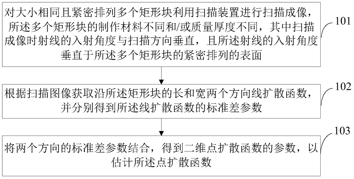
A point spread function and line spread function technology, applied in the field of point spread function estimation methods and systems, can solve the problems of low degree of automation and slow execution speed, and achieve the effect of improving clarity
- Summary
- Abstract
- Description
- Claims
- Application Information
AI Technical Summary
Problems solved by technology
Method used
Image
Examples
Embodiment 1
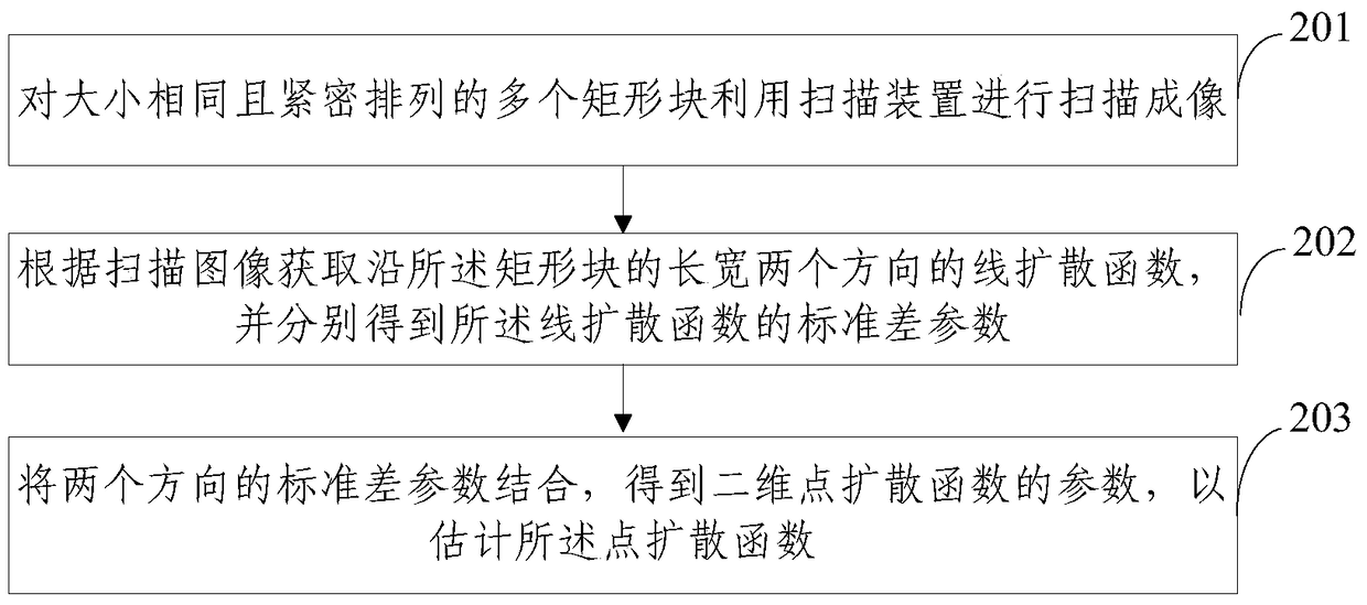
[0057] Embodiment 1 of the present invention provides a method for estimating the point spread function using a plurality of rectangular blocks of uniform plate-shaped materials with substantially the same size and different mass thicknesses. For details, see figure 2 ,include:
[0058] Step 201: Use a scanning device to scan and image a plurality of rectangular blocks of the same size and closely arranged.
[0059] In this step, multiple rectangular blocks composed of iron and polyethylene material blocks of different mass thicknesses are used for scanning imaging, and the scanned image is as image 3 Shown. The size of each material block is 200mm×200mm, and the first row is the mass thickness of 6g / cm. 2 , 8g / cm 2 , 10g / cm 2 Iron material; the first in the second row is the mass thickness of 4g / cm 2 The iron material, the second and the third are respectively with a mass thickness of 2g / cm 2 And 4g / cm 2 Polyethylene material; the first in the third row is the mass thickness of 3...
Embodiment 2
[0068] See Picture 10 The method for estimating the point spread function in Embodiment 2 of the present invention is basically the same as that in Embodiment 1, wherein, before step 1004 (corresponding to step 203 in embodiment 1 of the present invention), it further includes:
[0069] Step 1003: Average the standard deviation parameters of multiple line spread functions in the same direction, and combine the material and mass thickness of the rectangular block to obtain the average standard deviation parameter in this direction.
[0070] In this step, after performing the line spread function calculation and standard deviation parameter fitting of the foregoing steps on all the 6 internal vertical block boundaries and the 6 internal horizontal block boundaries in the first embodiment of the present invention, the standard deviations in the two directions can be respectively determined. The parameters are averaged to obtain the average standard deviation parameters in the horizont...
Embodiment 3
[0073] Embodiment 3 of the present invention provides a point spread function estimation system, see Picture 11 ,include:
[0074] The imaging unit 1101 is used for scanning and imaging a plurality of rectangular blocks of the same size and closely arranged by a scanning device. The materials of the plurality of rectangular blocks are different and / or the quality and thickness are different, and the incident angle of the rays during scanning and imaging is different from The scanning direction is vertical, and the incident angle of the rays is vertical to the closely arranged surfaces of the plurality of rectangular blocks;
[0075] The parameter obtaining unit 1102 is configured to obtain the line spread function along the length and width of the rectangular block according to the scanned image, and obtain the standard deviation parameters of the line spread function respectively;
[0076] The estimation unit 1103 is configured to combine the standard deviation parameters of the tw...
PUM
 Abstract
Description
Claims
Application Information
 - R&D
- Intellectual Property
- Life Sciences
- Materials
- Tech Scout
- Unparalleled Data Quality
- Higher Quality Content
- 60% Fewer Hallucinations
Browse by: Latest US Patents, China's latest patents, Technical Efficacy Thesaurus, Application Domain, Technology Topic, Popular Technical Reports.
© 2025 PatSnap. All rights reserved.Legal|Privacy policy|Modern Slavery Act Transparency Statement|Sitemap|About US| Contact US: help@patsnap.com


