A thermal management method and device for battery modules based on thermoelectric effect

A battery module and thermoelectric effect technology, applied in the direction of secondary batteries, circuits, electrical components, etc., can solve the problems of large heating surface heat, low air-cooled heat dissipation efficiency, slow thermal reaction speed, etc., and achieve high heat transfer coefficient , Buffering mechanical stress, fast thermal response

Active Publication Date: 2019-04-30
SHANGHAI UNIV OF ENG SCI
View PDF10 Cites 0 Cited by
  • Summary
  • Abstract
  • Description
  • Claims
  • Application Information

AI Technical Summary

Problems solved by technology

The disadvantage of this technical solution is that, since the heating surface of the semiconductor refrigeration element generates a large amount of heat, which includes both the heat absorbed by the cooling surface and the heat converted by the cooling electric power, the cooling efficiency of air cooling is low and the cooling efficiency is limited.
In addition, the semiconductor cooling element is far away from the battery, and the battery pack needs to be reheated by cooling the water tank and the water stored in the pipeline. The power consumption is large, the cooling capacity loss along the waterway is large, the thermal reaction speed is slow, and the cooling efficiency is insufficient.

Method used


Image

  • A thermal management method and device for battery modules based on thermoelectric effect
  • A thermal management method and device for battery modules based on thermoelectric effect
  • A thermal management method and device for battery modules based on thermoelectric effect

Examples


Embodiment Construction

[0057] The present invention will be further described below in conjunction with accompanying drawing.

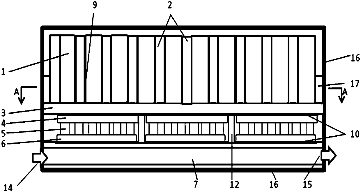
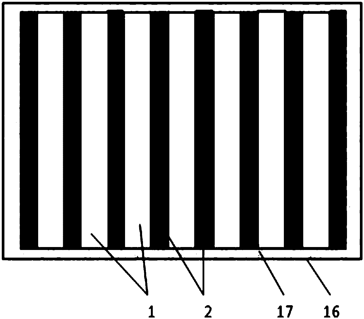
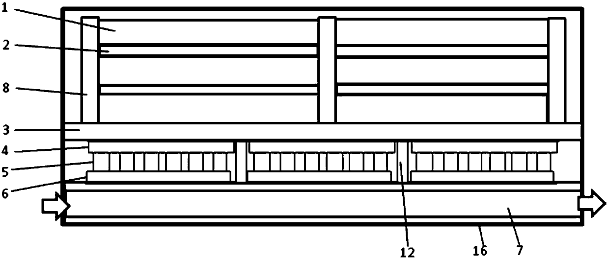
[0058] Such as figure 1 , image 3 and Figure 4 As shown, inside the battery pack box 16, the battery module 1, the heat conduction support plate 3, the semiconductor thermoelectric component and the liquid heat conduction channel 7 are arranged in close contact with each other from top to bottom, and a plurality of them are evenly distributed in the battery module 1. The heat conductor, the lower part of the heat conductor is close to the heat conduction support plate 3, forming a heat conduction path formed by the battery module-heat conductor-semiconductor thermoelectric component-liquid heat conduction channel, wherein:

[0059] The heat conduction support plate 3 is placed horizontally, and its surrounding edges are close to the inner wall of the battery pack box 16;

[0060] The semiconductor thermoelectric assembly includes a horizontal first heat exchange plate ...


PUM

PropertyMeasurementUnit
phase transition temperatureaaaaaaaaaa
thicknessaaaaaaaaaa
melting pointaaaaaaaaaa

Abstract

The invention discloses a battery module heat management method and apparatus based on a thermo-electric effect. A battery module, heat conductors, semiconductor thermal-electric assemblies and a liquid heat conducting channel form a heat conducting path in a battery pack box; the battery module heat management method comprises two working modes, including a refrigerating mode executed in a high-temperature environment and a heating mode executed in a low-temperature environment, wherein in the refrigerating mode, the temperature of the upper part of each semiconductor thermal-electric assembly is reduced to be lower than the environment temperature to form a refrigerating surface; the temperature of the lower part of the semiconductor thermal-electric assembly is increased to form a heat dissipation surface; the generated heat is discharged through the liquid heat conducting channel; in the heating mode, the temperature of the upper part of each semiconductor thermal-electric assembly is increased to form a heating surface; the battery module is heated through the heat conduction of the heat conductors to achieve a normal working temperature range; and meanwhile, the temperature of the lower part of each semiconductor thermal-electric assembly is reduced to form a heat absorption surface. The battery module heat management method and apparatus, by integrating refrigerating and heating into one body, is compact in structure and efficient in heat exchange, thereby ensuring that the battery can constantly work in the optimal temperature environment; and therefore, the battery module heat management method and apparatus have high application prospect.

Description

technical field [0001] The invention relates to the field of heat dissipation of vehicle energy storage batteries, in particular to a thermal management method and device for a battery module based on the thermoelectric effect. Background technique [0002] Energy storage batteries such as lithium-ion batteries have high energy density, small size, and long cycle life, and have great potential for application in electric passenger cars and commercial vehicles. However, since the temperature rise of the lithium-ion battery during charging and discharging affects its performance and cycle life, too high temperature may even cause thermal runaway, resulting in accidents such as spontaneous combustion and explosion. The temperature of the conventional lithium cobaltate cathode material battery needs to be controlled at 50 degrees Celsius. Within, to avoid thermal runaway and fire explosion, improve safety. With the advancement of battery materials and processes, although the op...

Claims


Application Information

Patent Timeline
Patent Type & Authority Patents(China)
IPC IPC(8): H01M10/613H01M10/615H01M10/6572H01M10/6568H01M10/6557H01M10/659H01M10/625H01M10/6551
CPCH01M10/613H01M10/615H01M10/625H01M10/6551H01M10/6557H01M10/6568H01M10/6572H01M10/659Y02E60/10
Inventor 张恒运隋杨龚元明牛甜甜
Owner SHANGHAI UNIV OF ENG SCI
Why Eureka
Try Eureka