Corrosion-resistant storage battery thermal insulation device

A heat insulation device and storage battery technology, which is applied in the direction of secondary batteries, circuits, electrical components, etc., can solve the problems that the storage battery cannot be used normally, affect the work progress, and increase the production cost, so as to slow down the temperature transfer efficiency, ensure the work progress, The effect of reducing production costs

Active Publication Date: 2017-02-01
WUHU HANGDA NETWORK IND CO LTD
View PDF4 Cites 2 Cited by
  • Summary
  • Abstract
  • Description
  • Claims
  • Application Information

AI Technical Summary

Problems solved by technology

For traditional dry-charged lead-acid batteries (such as automobile dry-charge batteries, motorcycle dry-charge batteries, etc.), distilled water should be added after a period of use to keep the dilute sulfuric acid electrolyte at a density of about 1.28g / ml; for maintenance-free batteries, the It is no longer necessary to add distilled water until the end of life. As a kind of storage battery, "lithium battery" has become the mainstream with the development of science and technology. Due to the very active chemical properties of lithium metal, lithium metal Processing, storage, and use have very high environmental requirements, and the existing vacuum insulation panels for lithium battery insulation devices are mostly fixed with glue. Under low temperature conditions, the glue is prone to deformation, resulting in loosening of the vacuum insulation panels. , so that the battery cannot be used normally, affecting the work progress and increasing the production cost

Method used


Image

  • Corrosion-resistant storage battery thermal insulation device
  • Corrosion-resistant storage battery thermal insulation device
  • Corrosion-resistant storage battery thermal insulation device

Examples


Embodiment Construction

[0019] The following will clearly and completely describe the technical solutions in the embodiments of the present invention with reference to the accompanying drawings in the embodiments of the present invention. Obviously, the described embodiments are only some, not all, embodiments of the present invention.

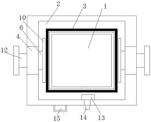
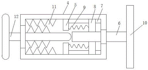
[0020] refer to Figure 1-3 , a corrosion-resistant battery heat insulation device, comprising a device body 1, the device body 1 is a hollow structure, a placement cavity 2 is provided in the device body 1, a vacuum heat insulation board 3 is movable in the placement cavity 2, and the device body 1 is away from One side of the placement cavity 2 is provided with a casing, and both sides of the casing are symmetrically provided with fixing grooves 4, and a pull rod 6 is movable in the fixing groove 4, and the pull rod 6 extends into the placement cavity 2, and the inner walls of the fixing groove 4 are symmetrically arranged on both sides. There is a mounting block 5...


PUM


Abstract

The invention discloses a corrosion-resistant storage battery thermal insulation device, which comprises a device body, wherein the device body is of a hollow structure; a placement cavity is arranged in the device body; a vacuum thermal insulation plate is movably arranged in the placement cavity; a housing is arranged at one side, far away from the placement cavity, of the device body; fixed grooves are symmetrically arranged in two sides of the housing; and a pull rod is movably arranged in each fixed groove. Through the addition of the fixed grooves, installation blocks, lock screws, springs, extrusion plates and the pull rods, the pull rods can be extruded by using the lock screws and drive the extrusion plates to move; and the extrusion plates fix the vacuum thermal insulation plate, so that use of an adhesive is avoided. Through the addition of a temperature sensor, a vacuum pump, an outlet pipe and a controller, when the working environment temperature is lower than the temperature required by a storage battery for working, the controller starts the vacuum pump and air in the placement cavity is discharged, so that the temperature transfer efficiency is reduced, the condition that the storage battery normally works in a low-temperature environment is ensured, the work progress is ensured and the production cost is reduced.

Description

technical field [0001] The invention relates to the technical field of heat insulation devices, in particular to a corrosion-resistant battery heat insulation device. Background technique [0002] A storage battery is a device that directly converts chemical energy into electrical energy. It is a battery designed to be rechargeable. It is recharged through a reversible chemical reaction. It usually refers to a lead-acid battery, which is a type of battery. , belonging to the secondary battery. Its working principle: When charging, the external electric energy is used to regenerate the internal active material, and the electric energy is stored as chemical energy. When it needs to be discharged, the chemical energy is converted into electric energy output again, such as the mobile phone battery commonly used in life. It uses a lead substrate grid filled with spongy lead (also known as a lattice body) as the negative electrode, a lead substrate grid filled with lead dioxide a...

Claims


Application Information

Patent Timeline
Patent Type & Authority Applications(China)
IPC IPC(8): H01M10/615H01M10/658
CPCH01M10/615H01M10/658Y02E60/10
Inventor 缪东伟
Owner WUHU HANGDA NETWORK IND CO LTD
Why Eureka
Try Eureka