
Distributed energy grid connection and reactive compensation composite control method

A technology of distributed energy and composite control, which is applied in the direction of AC network circuit, single-network parallel feeding arrangement, photovoltaic power generation, etc. It can solve the problems of high control cost, low equipment utilization rate, single function, etc., and achieve high grid connection efficiency Effect

Active Publication Date: 2017-02-01
SHANGHAI MUNICIPAL ELECTRIC POWER CO
View PDF9 Cites 20 Cited by
  • Summary
  • Abstract
  • Description
  • Claims
  • Application Information

AI Technical Summary

Problems solved by technology

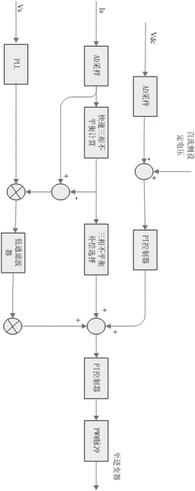
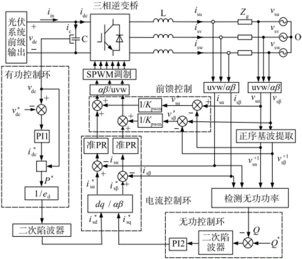
[0012] The present invention discloses a new scheme for distributed energy grid connection and reactive power compensation composite control method, through real-time measurement of the system current situation, through the corresponding algorithm to analyze the size of the active and reactive components of the system, and through comparison with the set adjustment target value , to control the switch of IGBT, thereby controlling the output of grid-connected and compensation current of each phase of the system, and finally make the system output the maximum grid-connected power in the mode of active power priority, and compensate the reactive current of the system first in the mode of regional reactive power priority. The active and reactive power compensation of the system is provided in the regional balance mode, which solves the problems of high control cost, single function and low utilization rate of equipment in the existing scheme

Method used


Image

  • Distributed energy grid connection and reactive compensation composite control method
  • Distributed energy grid connection and reactive compensation composite control method
  • Distributed energy grid connection and reactive compensation composite control method

Examples


Embodiment Construction

[0027] The present invention will be further described below in conjunction with accompanying drawing.

[0028] Photovoltaic grid-connected power generation systems generally include voltage and current sampling output by photovoltaic cell arrays, grid-connected inverter output current sampling, grid voltage sampling, power electronic converters and control systems, etc. The main circuit of the grid-connected inverter in the three-phase photovoltaic grid-connected power generation system generally adopts a voltage-type full-bridge structure, which is completely consistent with the main circuit of the conventional active reactive power compensation device. Therefore, the grid-connected and reactive power The compensation composite control device can effectively save equipment investment, simplify the system structure, and has excellent fast response characteristics of reactive power compensation, which plays an important role in improving the power supply capacity and quality of...


PUM


Abstract

The invention relates to a distributed energy grid connection and reactive compensation composite control method, which comprises the following processes of obtaining real-time grid voltage VS, system current IS and DC bus voltage Vdc through a collection module and then transmitting the real-time grid voltage VS, the system current IS and the DC bus voltage Vdc to a digital signal processor DSP; and obtaining reactive current and grid-connected current in a load through calculation, comparing the reactive current and the grid-connected current with a set adjustment target value, generating a fixed-frequency PWM pulse through a PI controller to drive an inverter power tube IGBT to be turned on and turned off, controlling output of each phase of grid-connected current and compensation current of a system, and outputting the maximum grid-connected power by the system in an active priority mode, firstly compensating the reactive current of the system in a regional reactive priority mode and providing the system with active compensation and reactive compensation in a regional balance mode. Through controlling output of each phase of grid-connected current and compensation current of the system, a distributed energy access device can be more intelligently used for a regional power grid and has the characteristic of high grid-connection efficiency.

Description

technical field [0001] The invention relates to a distributed energy grid-connected control method, in particular to a distributed energy grid-connected and reactive power compensation composite control method, which belongs to the field of grid-connected control of a power grid. Background technique [0002] With the continuous and high-speed development of the world economy, the demand for fossil energy in countries around the world is increasing, which leads to the rapid consumption of fossil energy. In addition, the large-scale development and utilization of fossil energy affect the global climate, and cause acid rain, greenhouse effects, ozone layer depletion and a series of environmental problems. Research and practice have shown that solar energy is inexhaustible, clean and harmless. It is the most reliable and effective green energy to solve the world's energy crisis and environmental pollution. It is predicted that photovoltaic power generation technology, which is...

Claims


Application Information

Patent Timeline
IPC IPC(8): H02J3/38H02J3/48H02J3/50
CPCH02J3/38H02J3/383H02J3/48H02J3/50Y02E10/56
Inventor 冯文俊胡海敏徐刚金琪李佳文杨振睿冯璇何正宇施俊尤智文
Owner SHANGHAI MUNICIPAL ELECTRIC POWER CO
Learn More