Charging method and control device suitable for lead-acid batteries for electric vehicles

A lead-acid battery, charging control technology, applied in the field of electric vehicles, can solve problems such as forgetting to pull out

Active Publication Date: 2019-02-05
任红雷
View PDF4 Cites 0 Cited by
  • Summary
  • Abstract
  • Description
  • Claims
  • Application Information

AI Technical Summary

Problems solved by technology

[0003] The purpose of the present invention is to provide a charging method and a control device suitable for electric vehicle lead-acid batteries, aiming at the overcharging problem caused by forgetting to unplug the power supply when charging electric vehicle batteries in the prior art. The charging method uses low-frequency pulses and time-added The range-limited charging mode realizes that the battery pack is fully charged and saturated at one time, and the charger can be turned off

Method used


Image

  • Charging method and control device suitable for lead-acid batteries for electric vehicles
  • Charging method and control device suitable for lead-acid batteries for electric vehicles
  • Charging method and control device suitable for lead-acid batteries for electric vehicles

Examples


Embodiment 1

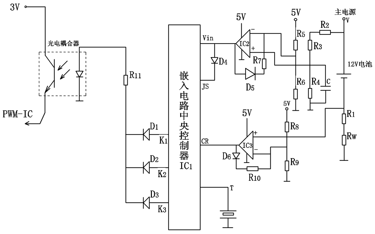
[0019] Embodiment 1: be suitable for the charging control device of lead-acid storage battery for electric vehicle, refer to figure 1 , including central controller IC1, GD photocoupler, voltage detection unit IC2 and battery internal resistance detection unit IC3; the central controller is provided with pins: Vin terminal, JS terminal, CR terminal, T terminal and K1, K2, Terminals K3 and Vin are connected to the output terminal of the voltage detection unit IC2 to receive the voltage signal corresponding to the battery terminal voltage sent from the output terminal of the voltage detection unit; terminals K1, K2, and K3 are the output terminals of the central controller, and K1 , K2, and K3 terminals are connected in parallel, the diode D1 is connected to the K1 terminal circuit, the diode D2 is connected to the K2 terminal circuit, the diode D3 is connected to the K3 terminal circuit, and the three circuits of K1, K2, and K3 terminals After parallel connection, the resistor ...


PUM


Abstract

The invention discloses a charging method and a control apparatus for a lead storage battery suitable for an electric vehicle, and belongs to the field of the electric vehicle. The control apparatus comprises a central control unit, a photoelectric coupler, a voltage detection unit and a battery internal resistance detection unit, wherein the central control unit is provided with pins of Vin end, JS end, CR end, T end and K1 end, K2 end and K3 end; the Vin end is used for receiving a voltage signal corresponding to a battery end voltage from the output end of the voltage detection unit; the K1 end, the K2 end and the K3 end are output ends of the central control unit; the primary PWM-IC working state of a charger is controlled through the photoelectric coupler; the JS end is a timing triggering end of the central control unit for timing charging periods; and the CR end is used for receiving a battery internal resistance state signal from the battery internal resistance detection unit. According to the charging method and the control apparatus, a low-frequency pulse charging mode limited by a time range is adopted, so that a common industrial phenomenon of early degradation of the capacity service life caused by a single backward failure in cyclic use of a 36-72v battery pack can be effectively solved; and instead, one-time balance charging saturation for the battery pack can be realized, and the charger can be turned off.

Description

technical field [0001] The invention belongs to the field of electric vehicles, and in particular relates to a charging method and a control device suitable for lead storage batteries used in electric vehicles. Background technique [0002] In the traditional charging method, when the electric vehicle charger is charging the battery, the battery is always charged before people unplug the power plug. Therefore, the battery will often be overcharged or undercharged. And we see that when the battery is fully charged, although the battery charging indicator turns from red to green, the charging circuit is not completely cut off, but the battery pack continues to be charged by the floating charge voltage in the later stage of charging, slow charging, and repeated long-term floating Slow charging will cause the battery pack to lose water seriously, deform and soften the battery, seriously affect the service life of the battery, and reduce the mileage of the battery. The existing ...

Claims


Application Information

Patent Timeline
Patent Type & Authority Patents(China)
IPC IPC(8): B60L58/13B60L58/25H01M10/44
CPCB60L53/00H01M10/441H02J7/0013H02J7/0036Y02E60/10Y02T10/70Y02T10/7072Y02T90/14
Inventor 任红雷
Owner 任红雷
Why Eureka
Try Eureka