Vertical grinding machine for glass fiber

A vertical mill and glass fiber technology, applied in grain processing and other directions, can solve the problems of large gap between the air ring and the retaining ring, pressure difference in the mill, and large current fluctuation of the main machine, so as to increase the grinding efficiency and avoid casualties. , the effect of increasing the operating load

Inactive Publication Date: 2017-02-08
SHANDONG FIBERGLASS GRP
View PDF6 Cites 2 Cited by
  • Summary
  • Abstract
  • Description
  • Claims
  • Application Information

AI Technical Summary

Problems solved by technology

The technology of the vertical mill is often operated in the way of large feeding and large slag discharge, and the mill runs smoothly. With the wear of the grinding roller and the lining of the grinding disc, the output of the mill gradually decreases from the original rated output of 8 tons per hour to 6-6 tons per hour. 8 tons per hour, or even less than 6 tons, can no longer meet the production needs. In addition, because the process relies on large feeding and large slag discharge to ensure the output of the mill, it will make the scraper plate, lower shell, and various parts of the mill lower. The material chute wears out quickly, resulting in a large maintenance workload. Although some slight adjustments have been made in the pressure and air volume, the increase in output is not obvious
[0005] The existing vertical mill structure such as Figure 5 As shown, its main structure includes separator discharge chute, grinding roller, separator rotor, dust collection pipe, upper wind ring, lower wind ring, scraper plate, slag discharge port, air inlet flow direction, main reducer, air inlet valve , feeding trough and pre-grinding belt scale, the working principle is that the motor drives the millstone to rotate through the main reducer, the pre-milling belt scale feeds the material into the mill, and falls on the millstone through the feeding trough, and the material falling on the millstone is under the influence of centrifugal force It is thrown to the edge of the grinding table under the action, and after being ground by the grinding roller, it falls from the gap between the air ring and the retaining ring to the slag discharge port at the bottom of the grinding table, and the wind from the air inlet valve blows up the fine particles after grinding and brings them into the separator for further processing. Screening, the qualified products are brought into the next process through the dust collection pipe, and the unqualified products fall back to the grinding table through the separator feeding pipe to continue grinding. The above-mentioned vertical mill has the following disadvantages in actual production: 1. If you want to maintain the thickness of the material layer of the mill, you must increase the feeding amount. If the feeding is small, there will be large current fluctuations in the main engine and vibration of the mill, which will reduce the efficiency; 2. The gap between the air ring and the retaining ring is large. As a result, the wind speed here is low, causing some qualified fine powder and small stones to be discharged out of the mill along with the slag discharge, and then put into the mill for regrinding through the pre-grinding bin, resulting in a large amount of slag discharge; The spacing is 750mm. When the unqualified fine powder falls back to the grinding table, the wind from the wind ring will directly lift it up, causing the pressure difference inside the mill to increase, the load on the separator increases, and the wear is accelerated; 4. Vertical mill There is no locking protection device at the manhole door, and staff misuse during shutdown for maintenance will cause serious personal injury or death

Method used


Image

  • Vertical grinding machine for glass fiber
  • Vertical grinding machine for glass fiber
  • Vertical grinding machine for glass fiber

Examples


Embodiment

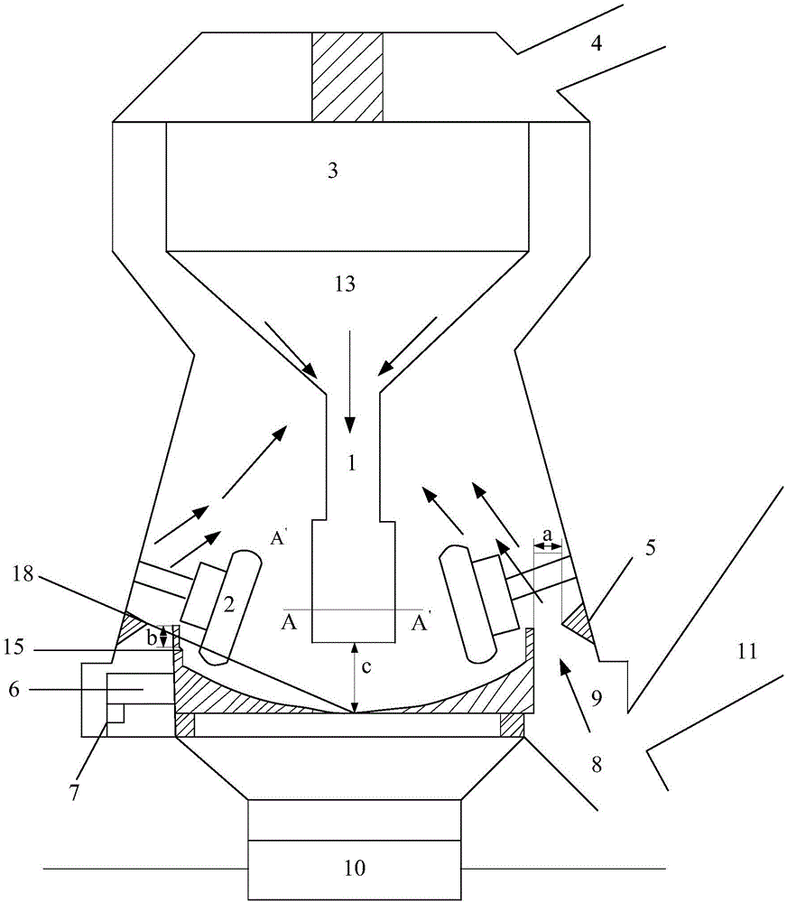
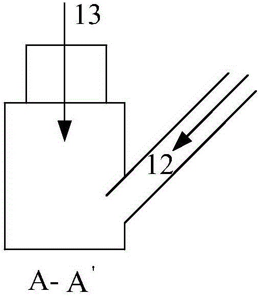
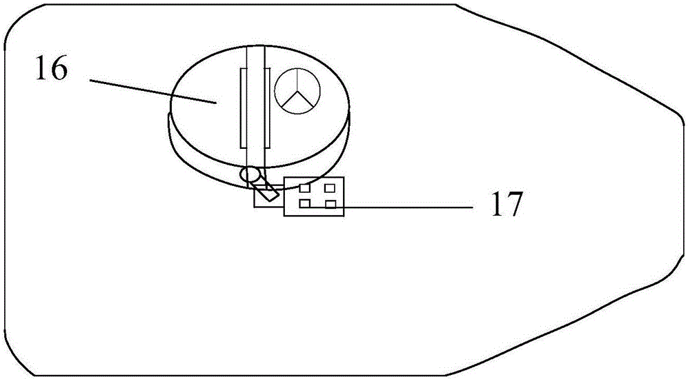
[0024] The vertical mill that this embodiment relates to is used for glass fiber, as figure 1 The main structure shown includes separator feeding pipe 1, grinding roller 2, separator rotor 3, dust collection pipe 4, upper wind ring 5, lower wind ring 6, scraper plate 7, slag discharge port 8, air inlet flow direction 9, Main reducer 10, air inlet valve 11, feeding chute 12, belt scale 14 before grinding, retaining ring 15, manhole door 16, travel switch 17 and grinding disc 18; the structure of each part and its interconnection are in the prior art The difference is that the separator feeding pipe 1 is extended vertically downward to a distance of 250 mm from the horizontal plane of the grinding disc 18, and the extension part of the separator feeding pipe 1 is a cylindrical steel pipe structure, and the diameter of the steel pipe is 426 mm; The groove 12 extends to the inside of the separator feeding pipe 1, and the extension part of the feeding groove 12 is in a sealed conn...


PUM


Abstract

The invention belongs to the technical field of grinding equipment and relates to a vertical grinding machine for glass fiber. The vertical grinding machine comprises a separator blanking pipe, a grinding roller, a separator rotor, a dust collecting pipe, an upper air ring, a lower air ring, a scraping plate, a dreg discharging hole, an air intake direction, a main speed reducer, an air intake valve, a feeding tank, a before-grinding belt scale, a material retaining ring and a manhole door; the vertical grinding machine is characterized in that the separator blanking pipe is vertically and downwards lengthened until the distance from the separator blanking pipe to the horizontal plane of a grinding disc is 250mm; the lengthened part of the separator blanking pipe is a cylindrical steel pipe of which the diameter is 426mm; the feeding tank extends inside the separator blanking pipe; the extension part of the feeding tank is hermetically connected with the part, in contact with the extension part of the feeding tank, of the separator blanking pipe; the height of the material retaining ring is increased by 140mm, and the clearance between each air ring and the material retaining ring is reduced to 30mm; a handle of the manhole door is additionally provided with a protective lock switch. The vertical grinding machine disclosed by the invention is reasonable, simple and convenient in structural design, low in cost, capable of improving the grinding efficiency and reducing the amount of discharged dregs, also capable of reducing abrasion, and capable of improving the safety as well during overhauling of equipment.

Description

[0001] Technical field: [0002] The invention belongs to the technical field of grinding equipment, and relates to a structure improvement technology of a vertical grinding mechanical equipment, in particular to a vertical grinding machine using glass fiber as a grinding raw material. [0003] Background technique: [0004] The crushing process of the vertical mill is the most important production process of the mill. The crushing process is that the grinding roller uses energy to squeeze, impact and grind the raw materials to grind out qualified fine powder for the application of the next process. The technology of the vertical mill is often operated in the way of large feeding and large slag discharge, and the mill runs smoothly. With the wear of the grinding roller and the lining of the grinding disc, the output of the mill gradually decreases from the original rated output of 8 tons per hour to 6-6 tons per hour. 8 tons per hour, or even less than 6 tons, can no longer mee...

Claims


Application Information

Patent Timeline
Patent Type & Authority Applications(China)
IPC IPC(8): B02C15/00B02C23/22
CPCB02C15/00B02C23/22B02C2015/002
Inventor 高贵恒李淑栋刘兴月齐元国
Owner SHANDONG FIBERGLASS GRP
Why Eureka
Try Eureka