Rotary locking element

A technology of rotating locking and locking disks, applied in the direction of fixtures, mechanical equipment, etc., can solve the problems of damage to the locking disk equipment, difficult to ensure the consistency of the locking disk, easy to scratch with peripheral equipment, etc., to achieve convenient operation, avoid connection difficulties, simple structure

Active Publication Date: 2017-02-08
STATE GRID CORP OF CHINA +2
View PDF6 Cites 2 Cited by
  • Summary
  • Abstract
  • Description
  • Claims
  • Application Information

AI Technical Summary

Problems solved by technology

[0003] When the servomotor is working normally, the locking disc and the piston rod of the servomotor are easy to scratch with the peripheral equipment during the action process, which may easily cause damage to the locking disc equipment; at the same time, after the locking disc is installed on the piston rod of the servomotor, it needs to be fixed. Connect and fix the locking disc with an immovable object such as a servomotor locally to lock, but at this time it is difficult to ensure that the bolt holes on the locking disc are consistent with the bolt holes of the servomotor body, and operation and maintenance are added when the servomotor locks the bolts difficulty

Method used


Image

  • Rotary locking element
  • Rotary locking element

Examples


Embodiment Construction

[0014] In order to better understand the present invention, the present invention will be further elucidated below in conjunction with this embodiment.

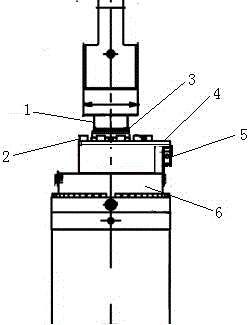
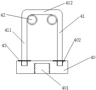
[0015] The present invention provides a rotary locking piece, which includes a rotary locking disc 40, a U-shaped cylindrical steel 41 and two sets of bolts 42. The rotary locking disc 40 is provided with a positioning groove 401 connected with a rotating body, and around the positioning slot 401 is provided with a socket Groove 402, the U-shaped cylindrical steel is integrally formed by a horizontal bar 411 and two vertical bars 412, and the nut of the bolt is welded on the inner side of the corner where the parallel bar and the vertical bar are connected. The bolt is used for the U-shaped cylindrical steel 41 and the servomotor For the connection between the bodies, the two vertical rods of U-shaped cylindrical steel are inserted into the insertion groove 402 of the rotating locking disk, and the lower end of the vertical ro...


PUM


Abstract

The invention discloses a rotary locking element. The rotary locking element is characterized by comprising a locking disc, U-shaped cylindrical steel and two bolts, wherein a location groove connected with a rotary body is arranged in the locking disc; a plurality of insertion-connection grooves are arranged around the location groove; the U-shaped cylindrical steel is formed through integrally moulding a parallel rod parallel to the locking disc and two vertical rods vertical to the locking disc; nuts of the bolts are connected to the U-shaped cylindrical steel; and the two vertical rods are inserted in the insertion-connection grooves of the locking disc. The locking disc is prevented from being liable to scrape with peripheral equipment during an action process with the rotary body through indirectly connecting the rotary locking disc with a servomotor body through the U-shaped cylindrical steel; and meanwhile, difficult connection between bolt holes in the locking disc and bolt holes of the servomotor body due to inconformity is avoided. The rotary locking element disclosed by the invention is simple in structure, convenient to operate, and suitable for industrialized production.

Description

technical field [0001] The invention relates to a fixing tool, in particular to a rotation locking piece. Background technique [0002] At present, there is a locking disc in the servomotor used in China. When the locking disc is installed, it is threaded into the piston rod. The locking disc can move together with the piston rod. The servomotor body locks the piston rod by connecting the locking disc, such as figure 1 . During daily installation or maintenance, the position of the piston rod can be adjusted by rotating the locking disc, so that the locking disc can be squeezed to the position switch installed on the servomotor, and the position switch signal is sent to the monitoring to confirm that the servomotor locking device is normal and reliable put in. [0003] When the servomotor is working normally, the locking disc and the piston rod of the servomotor are easy to scratch with the peripheral equipment during the action process, which may easily cause damage to th...

Claims


Application Information

Patent Timeline
Patent Type & Authority Applications(China)
IPC IPC(8): F16B1/02
CPCF16B1/02
Inventor 伍常林董海洋
Owner STATE GRID CORP OF CHINA
Why Eureka
Try Eureka