Injection molding machine

a molding machine and injection molding technology, applied in the field of injection molding machines, can solve the problems of difficult mounting of the detection device near the screw, difficult to place the sensor, and mold defects, and achieve the effects of reducing the time of deposit, easy adjustment, and avoiding mold defects

Inactive Publication Date: 2008-10-07
FANUC LTD
View PDF28 Cites 15 Cited by
  • Summary
  • Abstract
  • Description
  • Claims
  • Application Information

AI Technical Summary

Benefits of technology

[0012]The present invention provides an injection molding machine capable of adjusting a position of sensing a deposit level of the resin pellets remaining in the resin supplying hole with a simple structure, and further capable of sensing the deposit level of the resin pellets near a plasticizing screw.
[0022]With the injection molding machine as described above, there is no need to provide a separate sensor mounting mechanism on the heating cylinder or the machine main unit, and moreover, there is no need to use glass, an aperture or the like in a portion of the heating cylinder or the machine main unit in order to detect the resin. Further, there is no need for a complicated configuration requiring an expensive sensor, either, making it possible to use an inexpensive device structure. In addition, the sensor detection position can be easily adjusted to a position near the screw, enabling the deposited resin amount to be adjusted easily and moreover enabling injection to proceed using the minimum required amount of resin, enabling the deposited resin amount from the mouth of the hopper to the resin inlet to be decreased and the deposit time to be reduced. As a result, the absorption of moisture by and the decrease in temperature of the resin pellets can be reduced, virtually eliminating factors that lead to the occurrence of molding defects. Further, since the resin pellets do not strike the sensor detection surface with force, the sensor detection surface is not easily dirtied or scratched, thereby enabling any deterioration in detection performance or occurrence of sensor malfunction to be reduced.

Problems solved by technology

As a result, as the length of time the resin pellets remain inside the hopper and the resin supplying hole increases, the temperature of the resin pellets drops and the pellets collect moisture, which can cause molding defects.
However, with this method, it is possible to detect the resin pellets only when the topmost surface of the resin is on the upstream side of the machine main unit, and moreover, it is difficult to mount the detection device near the screw.
However, because this arrangement places the sensor on the outside of the resin supply cylinder, it is difficult to place the sensor near the screw, and thus it is difficult to measure the remaining resin amount.
However, with this method, to detect the resin level with the sensor it is necessary to make a portion of the resin supply cylinder out of glass or the like, which raises the cost of production.
Further, it is to be expected that a complicated structure is necessary to move the sensor close to the screw and that it is therefore difficult to measure the resin pellet deposit level near the screw.
As a result, with this method, since the sensor detection surface faces in the direction of the screw, resin pellets thrown up by the action of the screw frequently strike the sensor detection surface, dirtying and scuffing the sensor detection surface, with the risk of easy deterioration of the sensor detection capability.
In addition, since the resin deposit level must be measured by measuring the distance from the sensor to the resin, erroneous detection readings can easily occur when the resin is agitated by the action of the screw, and it is predicted that a high-accuracy sensor is required to prevent such erroneous measurement readings.

Method used


Image

  • Injection molding machine
  • Injection molding machine
  • Injection molding machine

Examples


Embodiment Construction

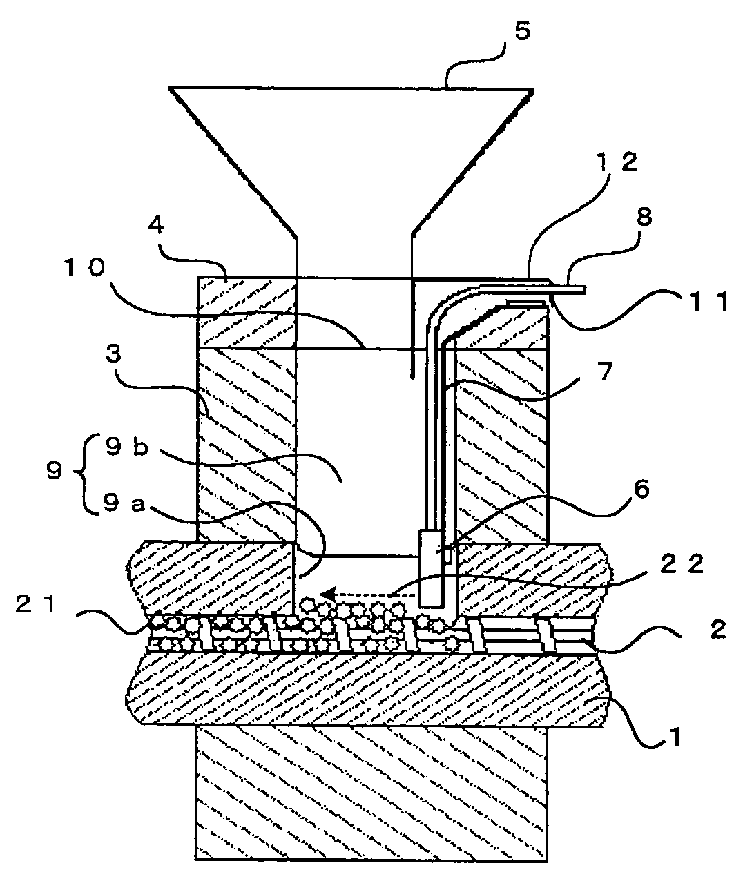
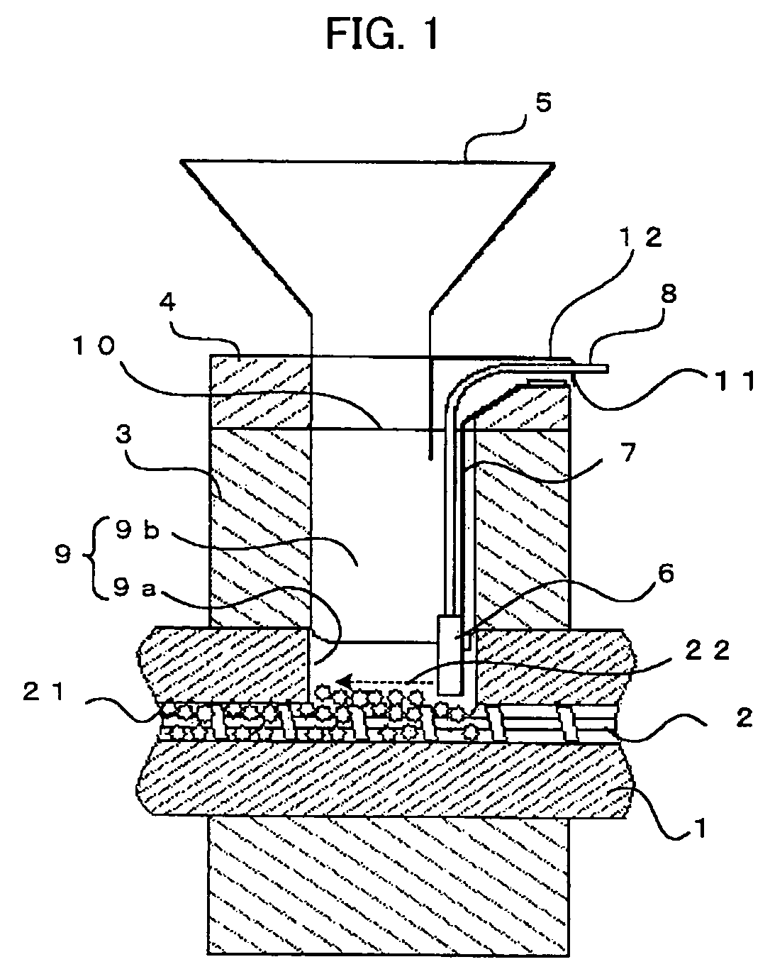
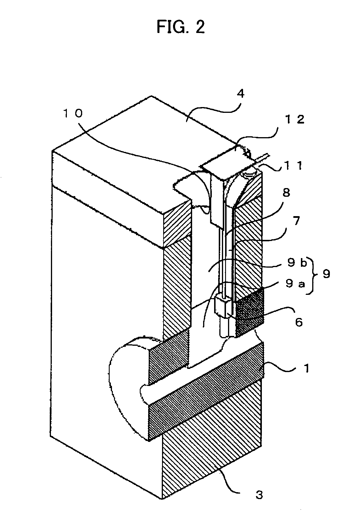
[0034]FIG. 1 is a sectional view of a resin supplying hole of an injection molding machine of a first embodiment of the present invention. FIG. 2 is a sectional perspective view of the resin supplying hole of the first embodiment.

[0035]A plasticizing screw 2 is inserted in a heating cylinder 1, a resin supplying hole 9a is provided on the heating cylinder 1 and a cooling jacket is provided on the outside of the heating cylinder 1. A resin supplying hole 9b provided on the cooling jacket 3 is disposed so as to communicate with the resin supplying hole 9a of the heating cylinder 1, and the heating cylinder 1 resin supplying hole 9a and the cooling jacket 3 resin supplying hole 9b are connected so as together to form a continuous resin supplying hole 9. In addition, a hopper plate 4 having a hopper 5 and that supplies resin pellets 21 supplied to the hopper 5 to a resin inlet 10 of the resin supplying hole 9 (specifically, the resin supplying hole 9b) is set and mounted on the cooling ...


PUM

PropertyMeasurementUnit
transparentaaaaaaaaaa
outer circumferenceaaaaaaaaaa
temperatureaaaaaaaaaa

Abstract

The invention provides an injection molding capable of adjusting a detection level with a simple structure and detecting a deposit level of the resin pellets near a plasticizing screw. A cooling jacket is mounted so that a resin supplying hole of the cooling jacket communicates with a resin supplying hole of a heating cylinder. A sensor head mounted on a sensor mounting plate is inserted into the resin supplying hole through a sensor insertion port provided on a hopper plate and a resin inlet and detects the deposit level of the resin pellets deposited in the resin supplying hole. Changing the extent of insertion of the sensor head enables the resin pellets deposit detection level to be changed, and further, enables the deposit level near the outer periphery of the screw to be detected. Setting the sensor detection direction perpendicular to the resin deposit direction enables dirtying of the sensor detection surface by the resin pellets to be reduced, thus enabling erroneous detection readings to be reduced.

Description

BACKGROUND OF THE INVENTION[0001]1. Field of the Invention[0002]The present invention relates to an injection molding machine, and more particularly to an injection molding machine having a sensor for detecting an amount of resin in a resin supplying hole that supplies resin to a heating cylinder.[0003]2. Description of the Related Art[0004]An injection molding machine repeatedly executes the steps of rotating a plasticizing screw inside a heating cylinder to knead and melt resin supplied to the interior of the heating cylinder and further metering the resin, then stopping screw rotation, advancing the screw and injecting melted resin into a mold, compressing, cooling and then opening the mold to remove the molded article.[0005]The resin pellets that are put into the heating cylinder are dried in a drier and put into a hopper by a resin feeder or the like, pass through a resin supplying hole mounted on the machine main unit or the heating cylinder, ground by a revolving screw and me...

Claims


Application Information

Patent Timeline
Patent Type & Authority Patents(United States)
IPC IPC(8): B29C45/18B29C45/47B29C45/76B29C48/92
CPCB29C45/18B29C45/76B29C47/92B29C31/02B29C2945/76096B29C2945/76107B29C2945/76183B29C2045/1891
Inventor TAKATSUGI, SATOSHISHIRAISHI, WATARUASAOKA, HIROYASUISHIKURO, TOSHIOIMAMURA, HIROSHI
Owner FANUC LTD
Why Eureka
Try Eureka