Robot hand for substrate transfer

a technology of robot hands and substrates, applied in the direction of hoisting equipment, program-controlled manipulators, thin material handling, etc., can solve the problems of bringing about an increase in cost, affecting the operation of the robot hand, and the substrate will be deviated in a certain direction, so as to achieve stable support, reduce friction force, and facilitate the effect of positional deviation of the substra

Active Publication Date: 2012-03-01
ULVAC INC
View PDF6 Cites 16 Cited by
  • Summary
  • Abstract
  • Description
  • Claims
  • Application Information

AI Technical Summary

Benefits of technology

[0009]According to the first embodiment, in case the substrate is flat or warped upward into a convex shape, the lower-surface peripheral edge of the substrate gets seated on the first seating surface. And the outer peripheral edge of the substrate comes into contact with the step along the periphery of the first seating surface, whereby the substrate can be prevented from positionally deviating. On the other hand, in case the substrate is warped downward into a concave shape, the peripheral edge of the substrate comes into contact with the step along the periphery of the first seating surface in a state of being upwardly inclined. Therefore, there is a possibility that the peripheral edge of the substrate will get over the step due to an inertia force at the time of stopping the movement of the robot hand. In the first embodiment, however, in case the substrate is warped downward into a concave shape, the lower surface of the substrate gets seated onto the second seating surface. As a result, due to a frictional resistance of the second seating surface, the positional deviation of the substrate can be suppressed.
[0034]By the way, when the raised band 33 is integrally formed on the robot hand 30, it becomes necessary to finish-grind, from the diametrically outer side and from the diametrically inner side, the curved surface 33a on the diametrically outer side and the curved surface 33a on the diametrically inner side, respectively, of the upper surface of the raised band 33. At this time, there is a possibility that a flat surface will remain at a diametrically intermediate portion on the upper surface of the raised band 33 or that a ridge line will be formed as a result of crossing of the diametrically outer curved surface 33a and the diametrically inner curved surface 33a at a diametrically intermediate portion on the upper surface of the raised band 33. Once this kind of ridge line is formed, the lower surface of the substrate S is easily scratched. As a solution, in this embodiment, the curved surface 33a is arranged to be ground such that a slight flat surface 33b remains at a diametrically intermediate portion of the upper surface of the raised band 33. According to this arrangement, there will be formed no ridge line, thereby preventing the substrate from getting scratched.

Problems solved by technology

However, in the above-mentioned arrangement described in the patent document 1, it becomes necessary to mount a large number of spring members on the robot hand, thereby bringing about an increase in cost.
This will be an obstacle to an attempt in improving the throughput.
In addition, if the robot hand is not held in a horizontal posture at the time of handing over, nonuniform load will be applied to the plurality of springs, resulting in a disadvantage in that the substrate will be deviated in a certain direction.

Method used


Image

  • Robot hand for substrate transfer
  • Robot hand for substrate transfer
  • Robot hand for substrate transfer

Examples


first embodiment

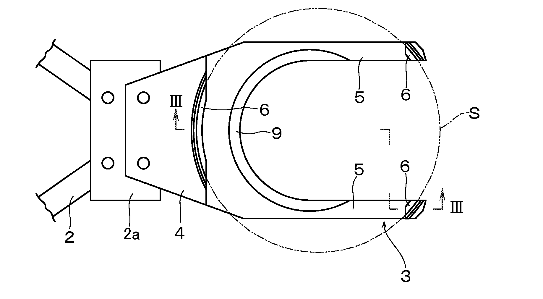
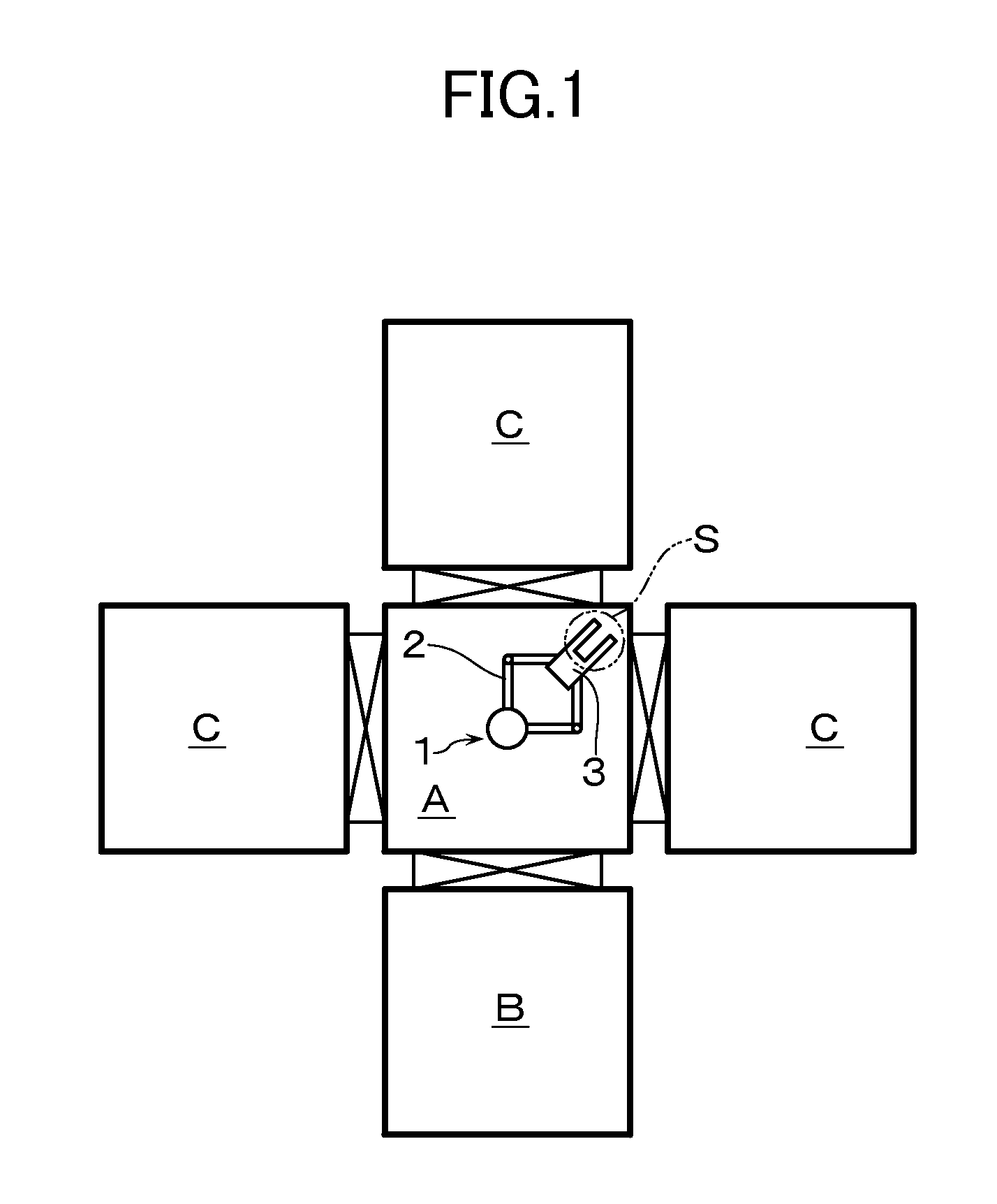
[0020]A description will now be made of an embodiment in which this invention is applied to a robot hand 3 to be connected to a robot arm 2 of a transfer robot 1 as shown in FIG. 1. In other words, the transfer robot 1 is disposed, like in the above-mentioned prior art, in a transfer chamber A. To a front end of the robot arm 2 there is attached, as shown in FIG. 2, a robot hand 3 through a gear box 2a.

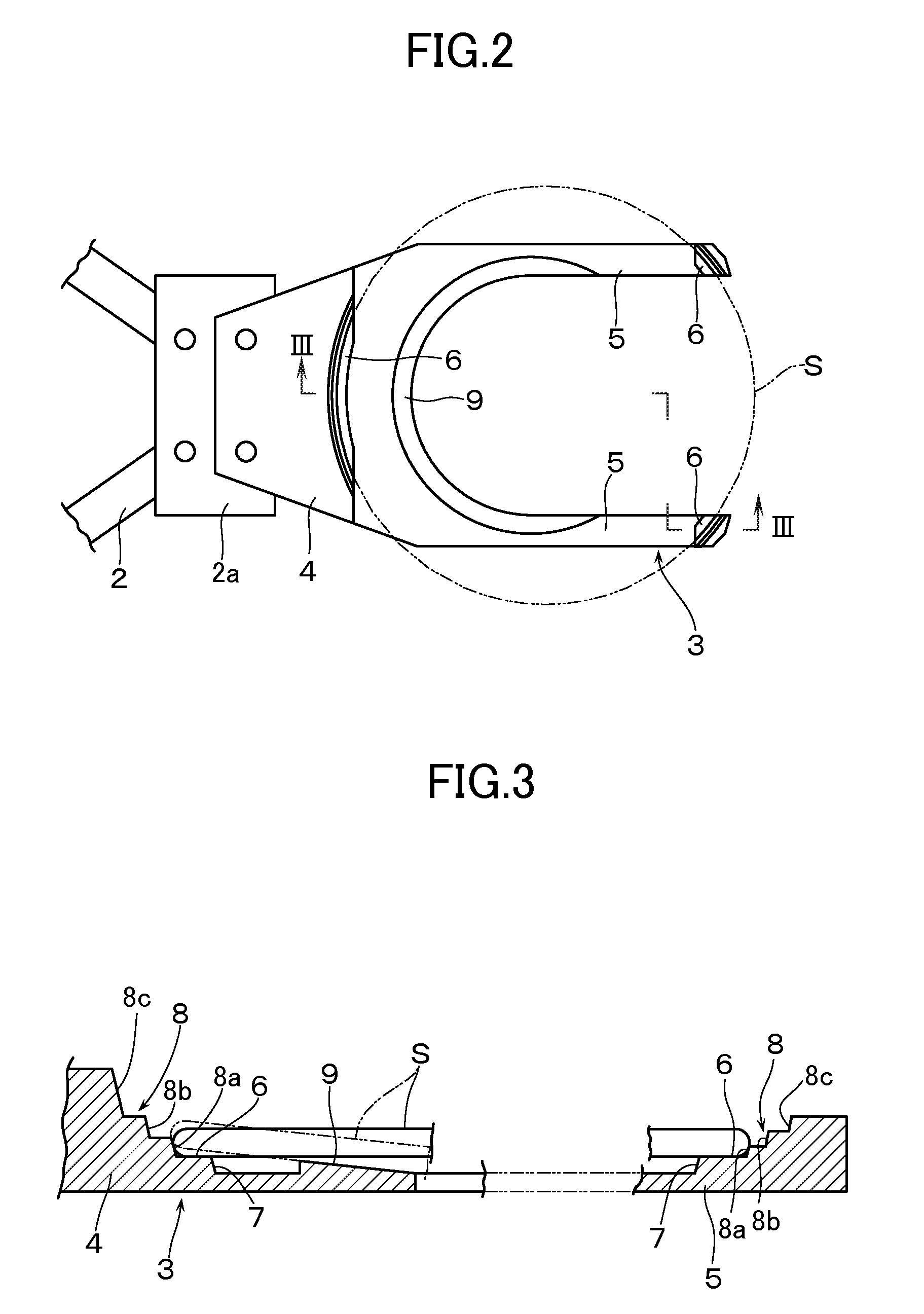
[0021]Since there is a case in which a substrate S is heated to a high temperature in a processing chamber C, this robot hand 3 has heat resisting properties and, in addition, is formed of a material having a high coefficient of friction such as a plate material, e.g., of Al2O3, SiO2, SiC and the like. Further, the robot hand 3 is provided with a pair of finger portions 5 which are bifurcated at, and are elongated forward from, a base end portion 4 that is connected to the gear box 2a.

[0022]At the base end portion 4 and at a front end portion of each of the finger portions 5, there...

second embodiment

[0030]On an upper surface of the robot hand 30, there is provided an upwardly raised band (projected strip) 33 which is elongated in a band shape along the same circle C of a predetermined diameter that is smaller than an outside diameter of the substrate S. It is thus so arranged that the substrate S can be seated on the raised band 33 coaxially with the circle C. The raised band 33 is provided separately in a plurality of portions on the circle C, i.e., separately in three portions at the base end portion 31, and at a pair of finger portions 32, 32. In this embodiment, the raised band 33 is formed integrally with the robot hand 30. Alternatively, the raised band 33 may be formed of rubber and the like into a body separate from the robot hand 30, and the raised band 33 may then be mounted on the upper surface of the robot hand 30. Considering the heat resisting properties, however, it is desirable to integrally form, like in this second embodiment, the raised band 33 on the robot h...


PUM


Abstract

There is provided a robot hand for substrate transfer in which the robot hand is so arranged that, even in case a substrate (S) gives rise to warping, the substrate (S) can be stably supported. On an upper surface of the robot hand there is formed a first seating surface on which is seated a lower-surface peripheral portion of the substrate (S) and, on a periphery thereof, there is formed an upwardly extended step. The step is provided with a plurality of stair-shaped stages. On an upper surface of the robot hand inwardly away from the first seating surface there is provided a second seating surface which is inclined downward toward the center of the substrate (S) such that a lower surface of the substrate (S) is seated on the second seating surface when the substrate (S) is warped downward into a concave shape.

Description

[0001]This application is a Divisional under 35 U.S.C. §120 of U.S. patent application Ser. No. 12 / 863,331, deposited on Jul. 16, 2010, which was a national phase entry under 35 U.S.C. § 371 of PCT Patent Application No. PCT / JP2009 / 051898, filed on Feb. 4, 2009, which claimed priority under 35 U.S.C. §119 to Japanese Patent Application No. 2008-025979, filed Feb. 6, 2008, all of which are incorporated by reference.TECHNICAL FIELD[0002]The present invention relates to a robot hand for substrate transfer in which the robot hand is mounted on a transfer robot for transferring a substrate such as a semiconductor wafer, a glass wafer and the like to support the substrate in a state of being mounted on the robot hand.BACKGROUND ART[0003]Conventionally, as an apparatus for performing various kinds of processing such as film-forming processing, etching processing and the like on a substrate, there is known a processing apparatus (a so-called cluster tool apparatus) which is constituted as s...

Claims


Application Information

Patent Timeline
Patent Type & Authority Applications(United States)
IPC IPC(8): H01L21/683
CPCY10S414/141H01L21/67742H01L21/68707B25J9/042B25J9/106B25J11/0095H01L21/68735
Inventor FUJII, YOSHINORINAKAMURA, SHINYA
Owner ULVAC INC
Why Eureka
Try Eureka