Gas conveying pipeline metering and pressure adjusting device and method

A technology for metering pressure regulation and gas transmission pipelines, which is applied in the pipeline system, gas/liquid distribution and storage, mechanical equipment, etc., and can solve the problems of increasing safety hazards and maintenance workload, prone to ice blockage, slow flow control response time, etc. problems, to achieve the effect of facilitating remote detection and control, real-time detection and control, and facilitating maintenance and repair

Active Publication Date: 2017-02-08
BC P INC CHINA NAT PETROLEUM CORP +2
View PDF9 Cites 31 Cited by
  • Summary
  • Abstract
  • Description
  • Claims
  • Application Information

AI Technical Summary

Problems solved by technology

For the first method, the flow meter and the control valve cannot realize one-to-one correspondence, the flow control response time is slow, and the system adjustment accuracy is low
For the second method, the accuracy of measurement data is low, and accurate measurement and control of flow cannot be realized; the flowmeter has no remote maintenance and remote fault diagnosis functions; there

Method used


Image

  • Gas conveying pipeline metering and pressure adjusting device and method
  • Gas conveying pipeline metering and pressure adjusting device and method

Examples


Example Embodiment

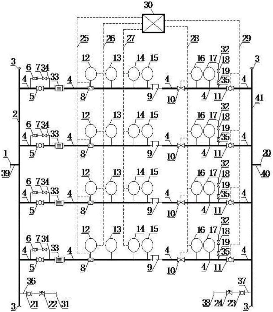
[0038] Example 1, such as figure 1 As shown, a gas pipeline metering and pressure regulating device according to an embodiment of the present invention includes: a first flange 1, a second flange 20, a first process pipeline 39, a second process pipeline 40, and a first manifold 2. The second header 41, the pipe cap 3, the multi-channel pressure and flow control device and the instrument junction box 30.

[0039] One end of the first process pipeline 39 is connected to the first flange 1, the other end of the first process pipeline 39 is connected to the first header 2, one end of the second process pipeline 40 is connected to the second flange 20, and the other end of the second process pipeline 40 Connected to the second header 41, both ends of the first header 2 and the second header 41 are connected to the cap 3, and four pressure and flow control devices are arranged between the first process pipeline 39 and the second process pipeline 40.

[0040] A first sewage pipeline 36 i...

Example Embodiment

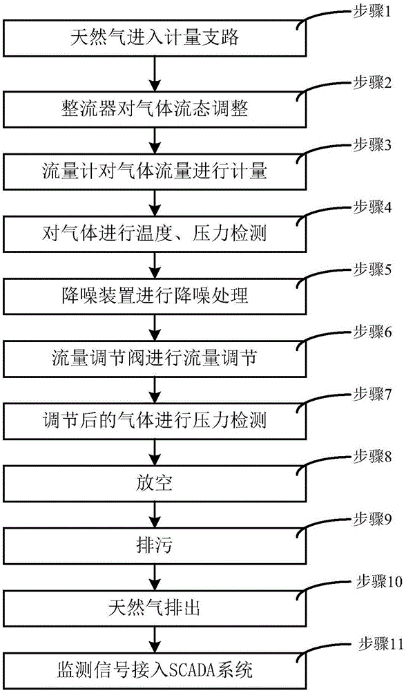
[0052] Example 2, such as figure 2 As shown, the present invention also provides a gas pipeline measurement and pressure regulation method, which specifically includes the following steps:

[0053] Step 1. Natural gas enters the first header 2 at the inlet, and enters the metering branch pipeline 4 through the first process valve 5 at the upstream inlet;

[0054] Step 2: Adjust the gas flow pattern through the rectifier 33;

[0055] Step 3: Perform flow measurement of the gas through the flow meter 8;

[0056] Step 4: Perform temperature and pressure detection on the gas through the first intelligent pressure transmitter 12, the local thermometer 13, the integrated temperature transmitter 14, and the first local pressure gauge 15;

[0057] Step 5: Perform noise reduction processing on the gas through the noise reduction device 9;

[0058] Step 6, adjust the flow of the gas through the flow control valve 10;

[0059] Step 7. Perform pressure detection on the adjusted gas through the seco...


PUM


Abstract

The invention discloses a gas conveying pipeline metering and pressure adjusting device. The gas conveying pipeline metering and pressure adjusting device comprises a first flange, a second flange, a first process pipeline, a second process pipeline, a first manifold, a second manifold, pipe caps, a multi-path pressure and flow control device and an instrument junction box. One end of the first process pipeline is connected with the first flange, and the other end of the first process pipeline is connected with the first manifold. One end of the second process pipeline is connected with the second flange, and the other end of the second process pipeline is connected with the second manifold. The pipe caps are connected to the two ends of the first manifold and the two ends of the second manifold. The multi-path pressure and flow control device is arranged between the first process pipeline and the second process pipeline. The invention further provides a gas conveying pipeline metering and pressure adjusting method. The gas conveying pipeline metering and pressure adjusting device and method have the beneficial effects that real-time detection and control over pressure and flow of a gas conveying pipeline station field can be achieved, high accuracy is achieved, running is stable, remote detection and control of an SCADA system are facilitated, and later maintaining and overhauling are facilitated.

Description

technical field [0001] The invention relates to the technical field of pipeline systems, in particular to a gas pipeline metering and pressure regulating device and method. Background technique [0002] In the gas pipeline station, in order to meet the normal operation of the pipeline, it is necessary to detect and control the flow and pressure of the gas transported by the pipeline. In the past, there are two main process methods: Method 1, the metering system and the pressure regulating system are respectively set up, and the two systems are relatively independent. Among them, the metering system mainly includes the front and rear gas collection pipes, the upstream and downstream straight pipe sections, the upstream and downstream shut-off valves and the flow rate. The pressure regulating system mainly includes the front and rear gas manifolds, upstream and downstream cut-off valves and regulating valves, and uploads the data of the metering system and pressure regulating ...

Claims


Application Information

Patent Timeline
IPC IPC(8): F17D1/02F17D3/01F17D3/18F17D5/00
CPCF17D1/02F17D3/01F17D3/18F17D5/005
Inventor 袁泉聂中文吴兆鹏单少卿于永志郭佳月王永吉祝岩青郑前徐建辉刘亮陈子庚许亮卢杨
Owner BC P INC CHINA NAT PETROLEUM CORP
Why Eureka
Try Eureka