Transverse wave full-focus ultrasonic imaging detection method for crack defect of steel plate weld
A technology for ultrasonic imaging detection and weld cracks, applied in the analysis of solids using sonic/ultrasonic/infrasonic waves, material analysis using sonic/ultrasonic/infrasonic waves, measurement devices, etc. Not ideal, unable to truly reflect the real shape of crack defects, etc., to achieve accurate and qualitative results
Inactive Publication Date: 2017-02-08
GUANGDONG GOWORLD
View PDF5 Cites 11 Cited by
- Summary
- Abstract
- Description
- Claims
- Application Information
AI Technical Summary
Problems solved by technology
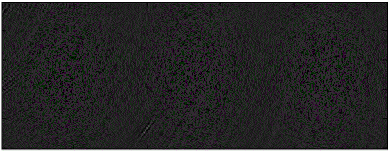
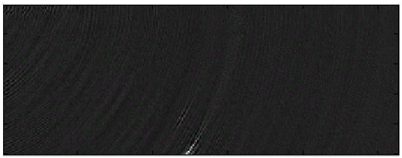
However, these detection methods and technologies are still not ideal, and the detection effect on defects is not intuitive enough, and cannot truly reflect the true shape of crack defects, such as figure 1 shown
The tandem crack detection operation is relatively complicated, and there is no intuitive imaging detection fu
Method used
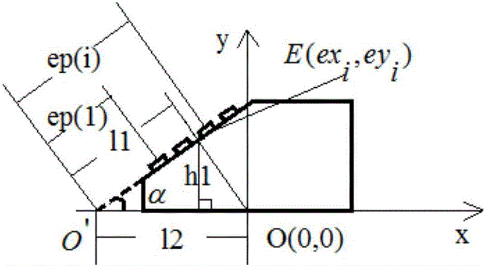
View moreImage
Smart ImageViewing Examples
Examples
 PUM
 Abstract
The embodiment of the present invention discloses a transverse wave full-focus ultrasonic imaging detection method for the crack defect of a steel plate weld. According to the invention, a probe with a transverse wave angle wedge block is placed on the parent metal of a to-be-detected steel plate butt weld workpiece. During the detection process of the probe, the direction of the probe is perpendicular to the direction of the weld. Without moving the probe, a phased array instrument acquires full-matrix echo signals inside the workpiece in real time. Meanwhile, the phased array instrument calculates the refraction propagation path of acoustic waves in real time according to a refraction point fast search algorithm for the propagation of acoustic waves in different workpieces and a reconstruction calculation model for crack defects. All the effective information of the crack defects is extracted out of an acquired information set in the distributed manner, and the extracted information is overlaid into the specific locations of real cracks in the workpiece. Therefore, the condition of crack defects in different directions inside the to-be-detected steel plate butt weld workpiece can be graphically and really reconstructed.
Description
Technical field [0001] The invention relates to the field of ultrasonic detection, in particular to a transverse wave full-focus ultrasonic imaging detection method for steel plate weld crack defects. Background technique [0002] Common cracks in butt welds of steel plates mainly include stress corrosion cracks, hydrogen-induced cracks and fatigue cracks. These cracks are mainly distributed longitudinally in the weld, and the cracks are easy to aggravate and propagate under various external forces, causing the steel plate to break. Compared with ordinary pores, slag inclusions and unfused defects, the detection of crack defects is much more complicated. Different types of cracks require different detection methods, and the scope of application of each detection method is limited. At present, there is no universally applicable method. Crack detection method. At present, many companies and research institutions at home and abroad have conducted a large number of research tests o...
Claims
Login to View More Application Information
Patent Timeline
 IPC IPC(8): G01N29/06G01N29/44
CPCG01N29/069G01N29/44G01N2291/0234G01N2291/0289G01N2291/267
Inventor 杨贵德王善辉杜南开陈建华林丹源
Owner GUANGDONG GOWORLD
Features
- R&D
- Intellectual Property
- Life Sciences
- Materials
- Tech Scout
- Unparalleled Data Quality
- Higher Quality Content
- 60% Fewer Hallucinations
Learn More Browse by: Latest US Patents, China's latest patents, Technical Efficacy Thesaurus, Application Domain, Technology Topic, Popular Technical Reports.
© 2025 PatSnap. All rights reserved.Legal|Privacy policy|Modern Slavery Act Transparency Statement|Sitemap|About US| Contact US: help@patsnap.com


