
Quick analysis method of electric performance of conformal load-bearing array antenna under dynamic load

An array antenna, dynamic load technology, applied in electrical digital data processing, special data processing applications, instruments, etc., can solve the problems of time-consuming structural analysis, delayed electrical performance analysis results, and real-time compensation of unfavorable antenna structural electrical performance.

Active Publication Date: 2017-02-08
JIANGSU LIANHAI COMM
View PDF4 Cites 8 Cited by
  • Summary
  • Abstract
  • Description
  • Claims
  • Application Information

AI Technical Summary

Problems solved by technology

However, when the service load of the antenna changes, it is necessary to re-analyze the structure, and then introduce the structural deformation information at different times into the calculation formula of the far-field pattern of the array antenna to obtain the corresponding electrical performance of the antenna, which will inevitably lead to calculation less efficient
Due to the time-consuming structural analysis, the results of electrical performance analysis will also lag behind, and the existing analysis methods are not conducive to realizing real-time compensation of electrical performance after antenna structure deformation

Method used


Image

  • Quick analysis method of electric performance of conformal load-bearing array antenna under dynamic load
  • Quick analysis method of electric performance of conformal load-bearing array antenna under dynamic load
  • Quick analysis method of electric performance of conformal load-bearing array antenna under dynamic load

Examples


Embodiment Construction

[0086] Specific embodiments of the present invention will be described in detail below.

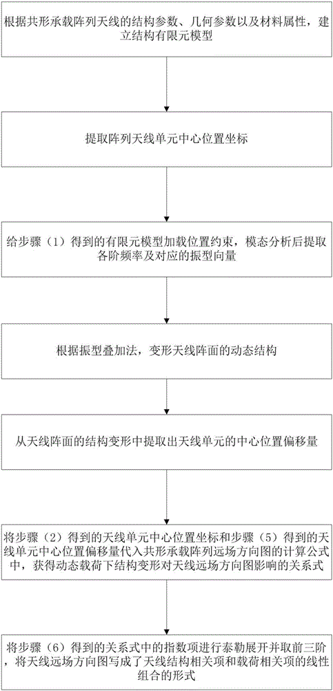
[0087] Such as figure 1 As shown, the rapid analysis method for the electrical performance of conformal load-carrying array antenna under dynamic load includes the following steps:

[0088] (1) According to the structural parameters, geometric parameters and material properties of the conformal bearing array antenna, a structural finite element model is established, where:

[0089] The geometric parameters of the conformal bearing array antenna include the size, position coordinates and number of elements of the array antenna;

[0090] The structural parameters of the conformal load-carrying array antenna include the height of the array and the cross-sectional area of ​​the array;

[0091] The material properties of the conformal loaded array antenna include the elastic modulus, Poisson's ratio and density of the material;

[0092] The structure of the conformal load-carrying array ant...


PUM


Abstract

The invention relates to a quick analysis method of the electric performance of a conformal load-bearing array antenna under a dynamic load. The quick analysis method comprises the following steps of: (1) establishing a structural finite element model; (2) extracting the central position coordinate rn of an array antenna unit; (3) loading a position constraint to the finite element model, and extracting each-order frequency [Omega]i and a mode-of-vibration vector after modal analysis is carried out; (4) expressing the dynamic structure deformation of an antenna array as [Delta]r([Beta], t)=Pq(t); (5) extracting the central position offset amount of the antenna unit; (6) substituting the central position coordinate rn of the antenna unit and the central position offset amount [Delta]rn([Beta, t]) of the antenna unit into the far-field pattern computational formula of the conformal load-bearing array antenna, and obtaining a relational expression which expresses the influence of the structure deformation on the far-field pattern of the antenna under the dynamic load; and (7) carrying out taylor expansion on an exponential term exp(jk.[Delta rn]([Beta, t])) in the relational expression, taking first three orders, and writing the far-field pattern of the antenna into a form of the linear combination of the structure relevant item and the load relevant item of the antenna.

Description

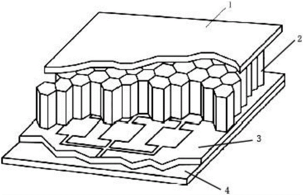
technical field [0001] The invention belongs to the technical field of antennas, and in particular relates to a method for quickly analyzing the electrical performance of a conformal bearing array antenna under dynamic loads. Background technique [0002] The conformal load-bearing array antenna refers to the use of an integrated composite molding process to embed a low-profile antenna array into the skin structure of various weapons and equipment to form a highly integrated smart skin antenna. The smart antenna has both mechanical bearing capacity and electromagnetic radiation capability. It is one of the indispensable key components in future weapons and equipment such as unmanned aerial vehicles, high-altitude airships, and new-generation early warning aircraft. [0003] Compared with the traditional array antenna, the conformal load-carrying array antenna has the advantages of load-carrying capacity, high integration, small space inside the equipment, good stealth perfor...

Claims


Application Information

Patent Timeline
IPC IPC(8): G06F17/50
CPCG06F30/23G06F30/367G06F2111/04
Inventor 宋立伟韩创黄进周金柱李鹏
Owner JIANGSU LIANHAI COMM
Learn More