Constant voltage and current limiting control circuit applied to gas discharge lamp ballast

A gas discharge lamp, constant voltage and current limiting technology, applied in the direction of electric light source, electrical components, light source, etc., can solve the problems of broken, high cost, inaccurate current limiting, etc., and achieve the effect of preventing saturation and good protection

Active Publication Date: 2017-02-08
KEBODA TECH CO LTD
View PDF5 Cites 0 Cited by
  • Summary
  • Abstract
  • Description
  • Claims
  • Application Information

AI Technical Summary

Problems solved by technology

The advantage of this scheme is that there are not many devices used, and the disadvantage is that the constant voltage accuracy is poor. During the working process, there will be several consecutive large duty cycles, and then several cycles of continuous shutdown, resulting in a relatively large fluctuation range of the output voltage.
Other constant voltage solutions use a dedicated DC / DC control chip to achieve constant voltage. The constant voltage control is very precise, and the output voltage has only a small switching ripple, but the cost of the DC / DC control chip is relatively high.
[0004] Among the current current limiting schemes, some current limiting schemes do not limit the current of the switch tube, which may cause the magnetic element to be saturated, and the life of the switch tube will be affected, or even directly broken; other current limiting schemes use the conduction of the switch tube The resistor is used as a current sampling resistor, and then works with a comparator to limit the current of the switch tube. Since the on-resistance of the switch tube is greatly affected by the driving voltage and temperature, this solution will be very inaccurate in current limiting.

Method used


Image

  • Constant voltage and current limiting control circuit applied to gas discharge lamp ballast

Examples


Embodiment Construction

[0012] The present invention will be described in detail below in conjunction with the accompanying drawings and specific embodiments.

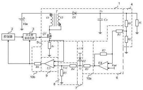
[0013] figure 1 A schematic circuit diagram of a constant voltage and current limiting control circuit applied to a gas discharge lamp ballast according to an embodiment of the present invention is shown. see figure 1 , The gas discharge lamp ballast includes a DC-DC conversion circuit 1 , a controller 2 , a switching tube drive circuit 3 and an output voltage sampling circuit 4 .

[0014] The DC-DC conversion circuit 1 includes a transformer T, a switch tube Q1, and a rectification and filtering circuit composed of a diode D1 and a capacitor Co. One end of the primary coil L1 of the transformer T and one end of the secondary coil L2 of the transformer T are connected to the first end of the switching tube Q1 respectively, and the other end of the primary coil L1 of the transformer T is connected to the DC input voltage Vin. The other end ...


PUM


Abstract

The invention discloses a constant voltage and current limiting control circuit applied to a gas discharge lamp ballast. The gas discharge lamp ballast comprises a DC-DC conversion circuit, a controller, a switching tube driving circuit and an output voltage sampling circuit. The DC-DC conversion circuit has a first output state and a second output state. The constant voltage and current limiting control circuit comprises a current sampling circuit, a differential amplifier circuit, a clamping circuit, a voltage division circuit and a comparison circuit. The current sampling circuit is connected with a second end of a switching tube. A first input end of the differential amplifier circuit is connected to the output end of the voltage sampling circuit, a second input end is connected with a reference voltage, and the output end is connected with the clamping circuit. The input end of the voltage division circuit is connected with the clamping circuit. A first input end of the comparison circuit is connected with the current sampling circuit, a second input end is connected with the voltage division circuit, and the output end is connected with the input ends of the controller and the switching tube driving circuit. Accurate constant current control and current limiting control can be realized on the basis of low cost.

Description

technical field [0001] The invention relates to ballasts for gas discharge lamps. Background technique [0002] Gas discharge lamps are increasingly used in automotive lighting. According to the characteristics of gas discharge, special ballasts need to be developed. In order to break down the gas, the ballast needs to generate a constant high voltage to act on the two poles of the gas discharge lamp. During the operation of the ballast, a current limiting protection circuit needs to be set to prevent the saturation of the magnetic components and protect the switch tube. [0003] Among the current constant voltage solutions, some constant voltage solutions use the cooperation of MCU and comparator to achieve constant voltage. The MCU gives the control PWM signal to the switch tube, and the comparator feeds back the output voltage signal of the DC-DC conversion circuit to the MCU. ; After the comparator detects that the output voltage exceeds the target output voltage, the M...

Claims


Application Information

Patent Timeline
Patent Type & Authority Applications(China)
IPC IPC(8): H05B41/285
CPCH05B41/2853
Inventor 阳彩阚予平
Owner KEBODA TECH CO LTD
Why Eureka
Try Eureka