A backwash lubricating oil filter

A filter and lubricating oil washing technology, which is applied in the direction of fixed filter elements, filter separation, chemical instruments and methods, etc., can solve the problems of increasing energy consumption, increasing the space occupied by equipment, harsh flow noise, etc., and achieve reduction Fluctuation of oil pressure and oil quantity, reduction of secondary flow and pressure pulsation, effect of reduction of lubricating oil loss

Active Publication Date: 2019-08-06
NO 719 RES INST CHINA SHIPBUILDING IND
View PDF7 Cites 0 Cited by
  • Summary
  • Abstract
  • Description
  • Claims
  • Application Information

AI Technical Summary

Problems solved by technology

[0003] (1) Large redundancy, bulky equipment, high oil loss rate
In order to ensure the continuous supply of lubricating oil, the current lubricating oil filter is mostly designed as a multi-chamber structure, of which 1 to 2 chambers are used as spare chambers, which are only put into use when the working chamber needs to be cleaned, resulting in a large degree of filter redundancy , the space utilization rate is low, and the space occupied by the equipment is virtually increased; at the same time, the lubricating oil in the original working chamber needs to be drained during flushing, and the loss rate of the lubricating oil is high
[0004] (2) The design of the flow channel is unreasonable, the flow resistance is large, and the noise is obvious
The existing lubricating oil filter does not pay enough attention to the design of the flow channel, which not only has a large resistance, but also increases the energy consumption of the system operation; at the same time, it produces harsh flow noise that seriously affects the health of the crew and passengers

Method used


Image

  • A backwash lubricating oil filter
  • A backwash lubricating oil filter
  • A backwash lubricating oil filter

Examples


Embodiment Construction

[0030] The present invention will be described in further detail below in conjunction with the accompanying drawings and embodiments.

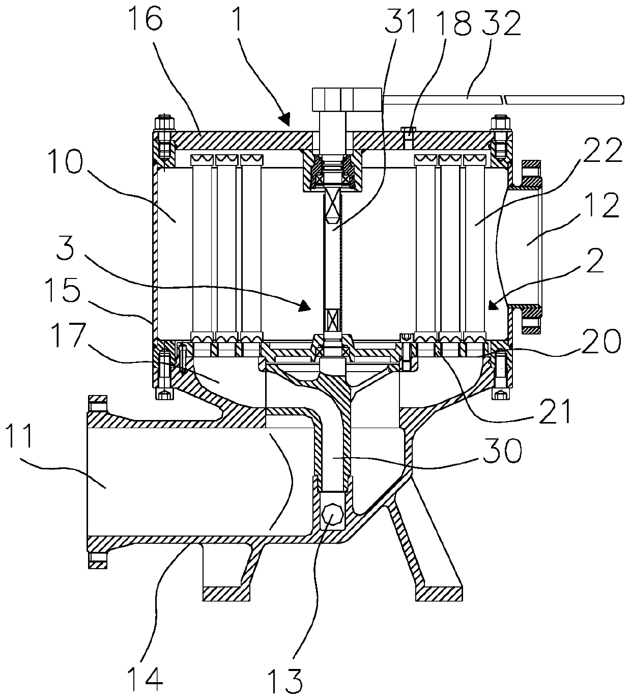
[0031] see figure 1 As shown, the embodiment of the present invention provides a backwash lubricating oil filter, comprising:

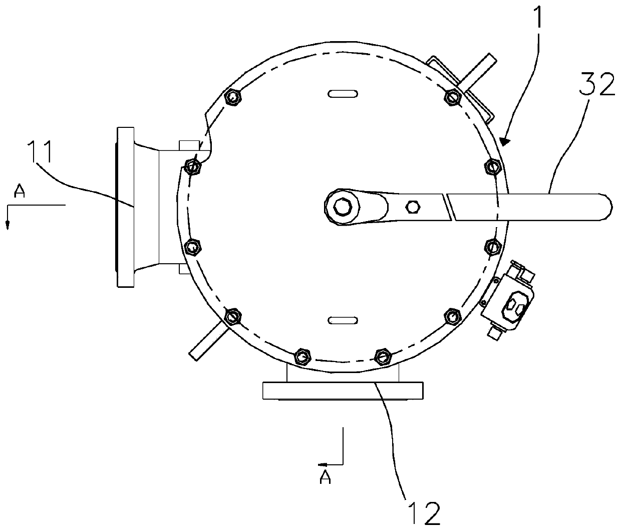
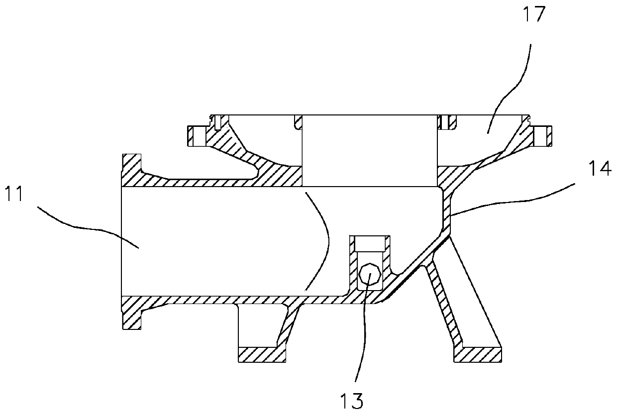
[0032] The filter body 1, the filter body 1 includes a base 14, a cylindrical housing 15 and an upper cover 16, the base 14 and the upper cover 16 respectively cover the upper and lower ends of the housing 15 to form a filter chamber 10, the base The side wall of 14 is provided with an inlet channel 11, the side wall of the housing 15 is provided with an outlet channel 12, and the bottom of the base 14 is provided with a sewage outlet 13, and the inlet channel 11, the outlet channel 12 and the sewage outlet 13 are connected with the filter chamber 10 respectively; The upper cover 16 is provided with an air release port 18 , and the air release port 18 communicates with the filter chamber 10 . Both the blowdown port ...


PUM


Abstract

The invention discloses a backwash lubricating oil filter, and relates to the technical field of power devices for ships. The backwash lubricating oil filter comprises a filter body, a filter element component and a rotating valve component, wherein a filtering chamber is formed inside the filter body; an inlet channel is arranged at the lower part of the filter body; an outlet channel is arranged at the upper part of the filter body; a drain outlet is formed in the bottom of the filter body; the inlet channel, the outlet channel and the drain outlet are respectively communicated with the filtering chamber; the filter element component is mounted inside the filtering chamber; the filter element component comprises a plurality of liquid inlets; the liquid inlets are communicated with the inlet channel to form a filtering channel; the rotating valve component is rotationally mounted on the filter body; the rotating valve component comprises a reverse flowing-out channel; at least one filtering channel corresponding to one liquid inlet is blocked by rotating the reverse flowing-out channel; the reverse flowing-out channel is communicated with the liquid inlet of the filtering component corresponding to the filtering channel and the drain outlet so as to form a reverse washing channel. The backwash lubricating oil filter has the advantages of being high in integration, small in size and low in noise.

Description

technical field [0001] The invention relates to the technical field of marine power devices, in particular to a backwash lubricating oil filter. Background technique [0002] The lubricating oil filter is used to filter mechanical impurities and oil particles in the lubricating oil to ensure that the quality of the lubricating oil meets the requirements of the lubricating oil user and avoid damage to the lubricating parts caused by impurities. For marine power units, the operating conditions are complex, the operating environment is harsh, and the requirements for equipment space and vibration and noise are high. At present, the existing marine lubricating oil filter has the following problems: [0003] (1) The redundancy is large, the equipment is bulky, and the loss rate of lubricating oil is high. In order to ensure the continuous supply of lubricating oil, the current lubricating oil filter is mostly designed as a multi-chamber structure, of which 1 to 2 chambers are u...

Claims


Application Information

Patent Timeline
Patent Type & Authority Patents(China)
IPC IPC(8): B01D29/52B01D29/66B01D35/12B01D35/30
CPCB01D29/52B01D29/66B01D35/12B01D35/30
Inventor 孟海波王春国邵燕赵旭峰陈景明闫海玲
Owner NO 719 RES INST CHINA SHIPBUILDING IND
Why Eureka
Try Eureka