Anti-corrosion ink high-efficiency stirring device for making antenna
A technology of anti-corrosion ink and stirring device, which is used in mixers with rotary stirring devices, accessories of mixers, transportation and packaging, etc. quality effect
- Summary
- Abstract
- Description
- Claims
- Application Information
AI Technical Summary
Problems solved by technology
Method used
Image

Examples
Embodiment 1
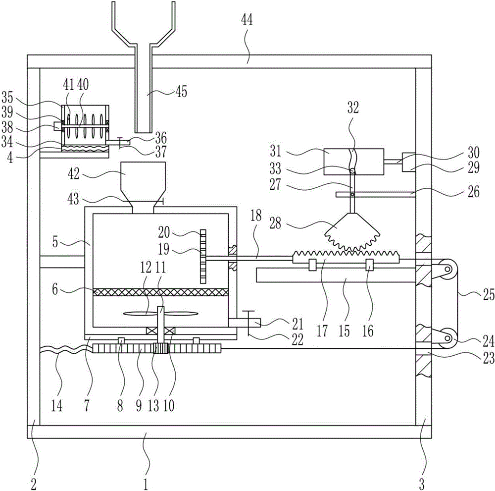
[0040] A high-efficiency stirring device for resist ink used in antenna production, such as figure 1 As shown, it includes bottom plate 1, left frame 2, right frame 3, heating device 4, stirring box 5, screen plate 6, first slide rail 7, first slider 8, first rack 9, first bearing seat 10. The first rotating shaft 11, the first stirring blade 12, the first gear 13, the first spring 14, the second slide rail 15, the second slider 16, the second rack 17, the moving rod 18, the straight plate 19, the first Discharge pipe 21, first electric control valve 22, fixed pulley 24, pull wire 25, pole 26, swing lever 27, sector gear 28, first motor 29, second rotating shaft 30, cylindrical cam 31, block 33, Heating wire 34, mixing box 35, second discharge pipe 36, second electric control valve 37, second motor 38, second bearing seat 39, stirring rod 40, second stirring blade 41, feed port 42, third Electric control valve 43, top plate 44 and lower hopper 45; left frame 2 and right frame...
Embodiment 2
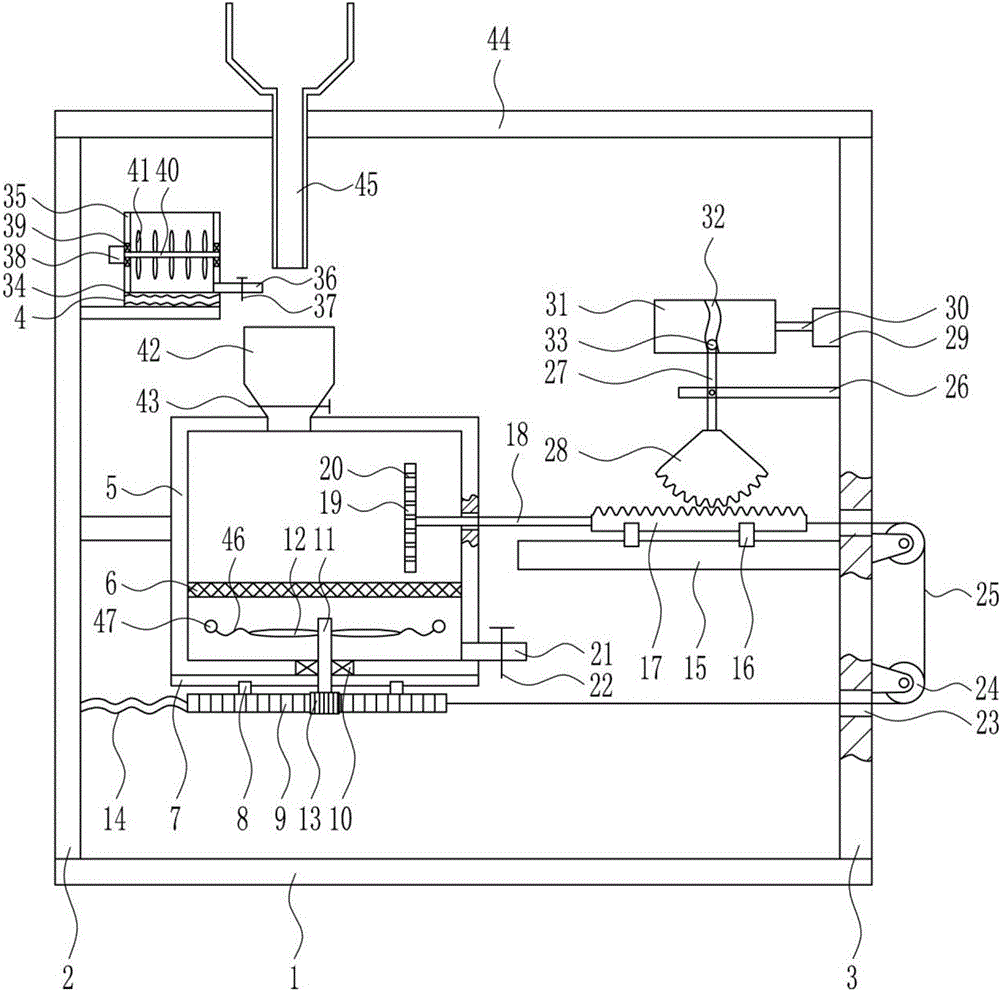
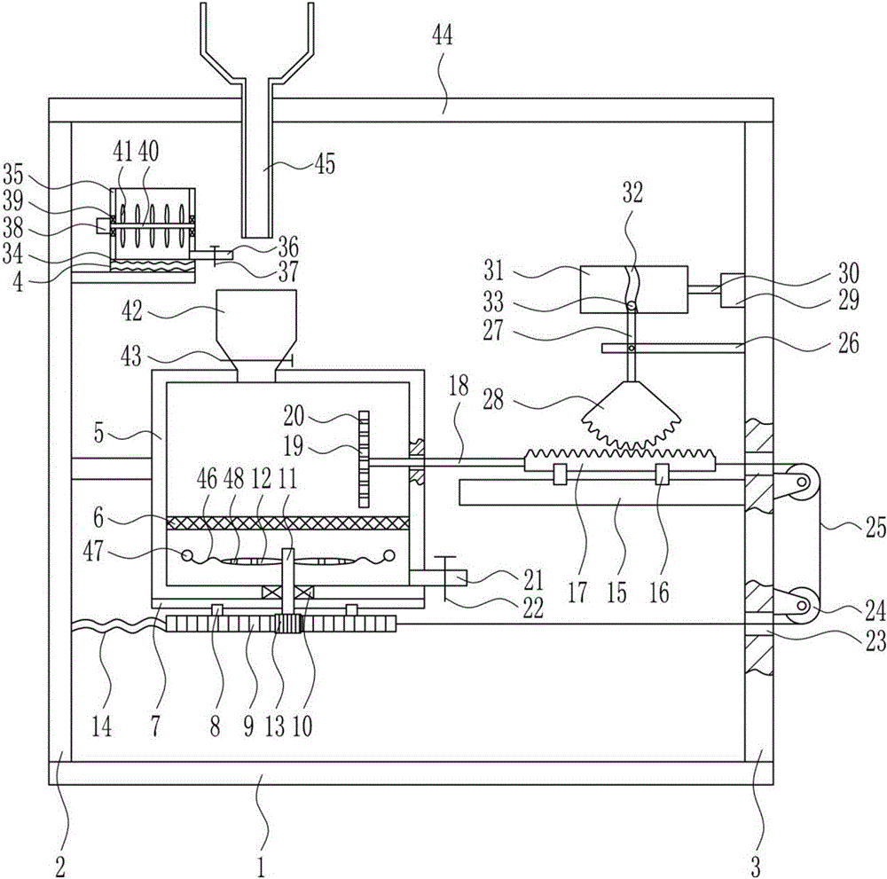
[0042] A high-efficiency stirring device for resist ink used in antenna production, such as Figure 1-9 As shown, it includes bottom plate 1, left frame 2, right frame 3, heating device 4, stirring box 5, screen plate 6, first slide rail 7, first slider 8, first rack 9, first bearing seat 10. The first rotating shaft 11, the first stirring blade 12, the first gear 13, the first spring 14, the second slide rail 15, the second slider 16, the second rack 17, the moving rod 18, the straight plate 19, the first Discharge pipe 21, first electric control valve 22, fixed pulley 24, pull wire 25, pole 26, swing lever 27, sector gear 28, first motor 29, second rotating shaft 30, cylindrical cam 31, block 33, Heating wire 34, mixing box 35, second discharge pipe 36, second electric control valve 37, second motor 38, second bearing seat 39, stirring rod 40, second stirring blade 41, feed port 42, third Electric control valve 43, top plate 44 and lower hopper 45; left frame 2 and right fr...
PUM
| Property | Measurement | Unit |
|---|---|---|
| Bottom diameter | aaaaa | aaaaa |
Abstract
Description
Claims
Application Information
 - R&D
- Intellectual Property
- Life Sciences
- Materials
- Tech Scout
- Unparalleled Data Quality
- Higher Quality Content
- 60% Fewer Hallucinations
Browse by: Latest US Patents, China's latest patents, Technical Efficacy Thesaurus, Application Domain, Technology Topic, Popular Technical Reports.
© 2025 PatSnap. All rights reserved.Legal|Privacy policy|Modern Slavery Act Transparency Statement|Sitemap|About US| Contact US: help@patsnap.com